×
INTELLIGENT WORK FORUMS
FOR ENGINEERING PROFESSIONALS

Log In

Come Join Us!

Are you an
Engineering professional?
Join Eng-Tips Forums!
  • Talk With Other Members
  • Be Notified Of Responses
    To Your Posts
  • Keyword Search
  • One-Click Access To Your
    Favorite Forums
  • Automated Signatures
    On Your Posts
  • Best Of All, It's Free!

*Eng-Tips's functionality depends on members receiving e-mail. By joining you are opting in to receive e-mail.

Posting Guidelines

Promoting, selling, recruiting, coursework and thesis posting is forbidden.

Students Click Here

Massive Changes to My Engine Design !

Massive Changes to My Engine Design !

Massive Changes to My Engine Design !

(OP)
All,

You may recall the challenges I was facing with installing a fuel injector in every cylinder of my engine; with a 49.5cc engine comprised of 6 cylinders, each was only 8.25cc and required a micro-fuel injector that had good enough spray pattern to yield a well mixed homogeneous fuel/air mixture. After working through the injector design, I decided the injector approach was simply too risky for a small engine such as my prototype. I thus went off to work up an alternate architecture using a single larger fuel injector to feed an intake manifold shared between all cylinders. This puts the fuel injector into the realm of components I can buy off-the-shelf.

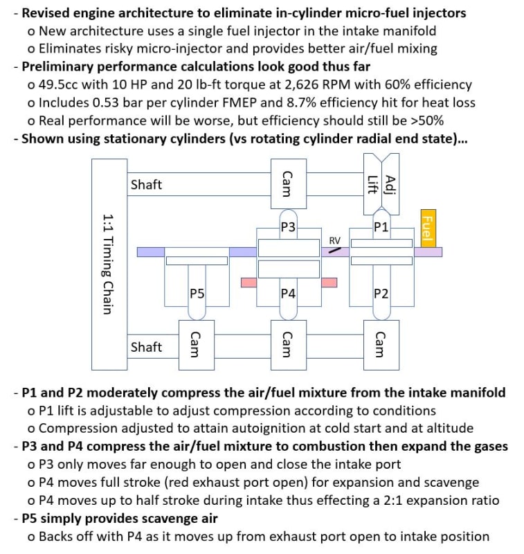
The use of a shared intake manifold with premixed fuel/air unfortunately requires use of two air pump pistons in place of the one in the prior architecture; one air pump piston for scavenge fed with air alone and another for intake fed with mixed fuel and air. The use of separate pistons increases complexity because each must now be driven by independent cam lobes (not a big deal) but the two pistons don't affect performance much because the pistons are very light and operate at comparatively low pressure. They do, of course add some volume, but not as much as I expected. Since I was reworking everything, I decided to exploit the separate cams on intake and scavenge to mechanize over expansion (to increase efficiency) and simplify the means by which I was compensating for cold-start and altitude (which both require variable compression ratio). All of these changes are evident in the annotated illustration below.

While I'm bummed at the amount of work this change is taking to update math models, CAD models, CFD, and FAE, I'm happy with the performance and glad to have caught the problems in the prior architecture *before* I started cutting metal!

Comments, suggestions, and questions are encouraged!

Rod
Replies continue below

Recommended for you

RE: Massive Changes to My Engine Design !

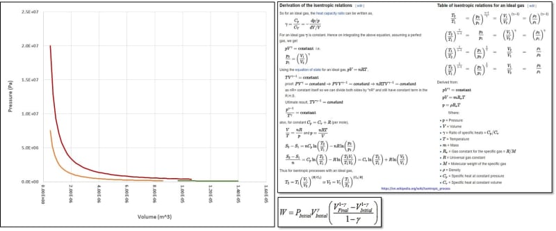
A p-v diagram would be nice.

How are you calculating thermal efficiency?

2:1 expansion ratio with 60% TE???

je suis charlie

RE: Massive Changes to My Engine Design !

(OP)
The estimates are from my course thermodynamic model. Performance is estimated by calculating isentropic relations for start/end volume, pressure, and temperature for each of the major cycles that produce or consume significant work (pump compression, charge compression, combustion/expansion) at sea level. Gamma (y, ratio of specific heats) is calculated for each step based on temperature. Work (W) is then calculated for each step then summed and IMEP calculated. FMEP is the average of Heywood and Ricardo figures for typical engines. BMEP is then calculated and used to calculate HP, Torque, efficiency, and BSFC. Next, I reduce efficiency by 8.7% to reflect typical heat loss in an opposed piston engine then recalculate performance at the lower efficiency. I don't bother calculating air pump intake or the scavenge cycle because both are low pressure processes using low tension rings and should have little impact on total work (assuming properly sized ports).

I'm now updating the more detailed model that uses actual cam timing and Hohenberg's heat transfer coefficient to calculate heat loss for each one-half degree of the cycle. This model is a lot more work because it incorporates a host of detailed characteristics (port area, cam timing, reciprocating mass, cam loads, etc.), so I never undertake it until the preliminary model looks good (meaning it shows excess performance relative to goals).

I misspoke regarding expansion ratio (the ratio of P3|P4 volume at exhaust vs volume at intake). Though I *set* it at 2:1, the preliminary model limits expansion to ensure minimum conditions when the exhaust port first opens (the lesser of 4 bar pressure or 850F temperature). As it stands, the compression ratio of the air pump (P1|P2) is 1.44:1 while the main cylinder (P3|P4) has a compression ratio of 18:1 and an expansion volume equal to 1.16x the intake volume before compression starts.

RE: Massive Changes to My Engine Design !

So an expansion ratio of 18 x 1.16 = 20.88:1?

That makes a bit more sense.

je suis charlie

RE: Massive Changes to My Engine Design !

I'm waiting for the big change. And of course the running prototype. The main cam drive system won't last or is it now a crankshaft?

RE: Massive Changes to My Engine Design !

(OP)
gruntguru, It seems I've abused terms again. Yes, the ratio of volumes from combustion to opening of the exhaust valve is 20.88:1.

enginesrus, I spent months struggling to explore the micro-fuel injectors, and I'll spend months reworking all the details of the new arrangement having 5 pistons per cylinder set in place of the prior 3, so I think it's a pretty big change. A working prototype is my only objective, but it's still going to be a while; a new engine design based on existing and well proven concepts typically takes a *team* of engineers a couple of years, so my progress is obviously going to be markedly slower. I acknowledge I may well fail for any number of reasons, but I don't know of any that are assured as you imply in your cam comment. The mass, travel, and acceleration of the pistons in the prototype engine are well below those associated with the valve train in a larger conventional engine, so I don't expect premature failure of the cams to be an issue. The cams may become a critical issue at some point in larger engines, but I'm not planning to build anything larger than about 650cc and am open to using multiple rotors, so the cams may never be an issue. Only time, prototypes, and endurance testing will tell.

Rod

RE: Massive Changes to My Engine Design !

I guess its my opinion, but the cam as used in the normal reciprocating engines that we all know, is a weak point especially in racing applications, and other than the exhaust stroke it is not loaded as much as what a system like yours will be, it is just not a good way to convert reciprocating motion to rotary motion, and actually there is much to be considered in cam design such as accelerations and such. You would be better off using the technique that some hydraulic motors do.

RE: Massive Changes to My Engine Design !


If a conventional diesel engine had an expansion ratio of 20.88:1 (to the point when the exhaust valve opened) it would mean that the geometrical compression/expansion ratio would be about (at a guess) 40:1. You get the same effect with a conventional petrol/ICE engine - if the CR is 9:1 and the temps of combustion and exhaust are typically about 1900/700 degrees C - this equates to about an actual effective 4:1 expansion ratio. Sorry about the guesses but I have worked it out more accurately before and I recall that the figures are something like these.

I still haven't seen a general simple diagram of how the engine operates (but I may have missed it).

RE: Massive Changes to My Engine Design !

(OP)
BigClive,

I may have changed my target exhaust temp since I wrote the post, but I don't think I've changed it much. Here are the key parameters...

Air Pump
Start Volume: 2.76E-05 m3
Start Pressure: 101,493 Pa
Start Temp: 288K
Air Mass: 3.39E-05 kg (note some will be lost in manifold during transfer to compression cylinder)
y: 1.380 (gamma, ratio of specific heats)
End Volume: 2.25E-05 m3
End Pressure: 134,175 Pa
End Temp: 311K

Compression
Start Volume: 1.01E-05 m3
Start Pressure: 134,175 Pa
Start Temp: 311K
Air Mass: 1.52E-05 kg (mass in 12.375 cc volume at sea level pressure and temp)
y: 1.332 (gamma, ratio of specific heats)
End Volume: 4.88E-07 m3
End Pressure: 7,613,756 Pa
End Temp: 852K

Combustion and Expansion
Start Volume: 4.88E-7 m3
Start Pressure: 21,000,000 Pa (210 bar, a design max)
Start Temp: 2,000K (peak combust temp, a design max)
Air mass: 1.52E-05 kg
y: 1.280 (gamma, ratio of specific heats)
End Volume: 1.35E-05 m3
End Pressure: 298,979 Pa
End Temp: 788K (chosen to ensure catalytic converter operation and at least 2 bar delta to ambient pressure).

Cylinder Performance
Work: 11.35 J per each of four cylinders (includes expected 17.4% heat loss)
IMEP: 9.17 bar per each of four cylinders
FMEP: 0.53 bar per each of four cylinders (average of Heywood and Ricardo)
BMEP: 8.65 bar

Engine Performance
Displacement: 49.5 cc in all (four) cylinders combined (12.375 cc each)
HP: 10.1 all cylinders combined
Torque: 20.1 lb-ft all cylinders combined
Equivalency: 0.403 (36.4:1 air to fuel ratio)
Efficiency: 60%
BSFC: 0.230 lb/hr/HP

Fuel Characteristics
Type: Diesel #2
LHV: 42.8 MJ/kg
Stoichiometric AFR: 14.5:1
Ignition Delay at 311K: 5.2 ms
Ignition Delay at 852K: 1.0 ms

From the above, the Air Pump compression ratio is 1.22:1 and the Cylinder compression ratio is 20.72 yielding a combined 27.7:1 compression ratio while the expansion ratio is 27.7:1. I'm not sure if, when discussing expansion ratio, it should be compared to Air Pump * Cylinder compression ratio or just Cylinder compression ratio. It's really only a matter of terms, however, and the safest way is to provide all three figures as I have. Regardless of wording, the result is calculated as the air moves through the engine stages and I'm reasonably confident my calculations are correct. It's very important in reviewing these figures to note the engine uses HCCI combustion, the closest approximation to constant volume combustion, which does not spray fuel during the expansion stroke.

Rod

P.S. The illustration I posted at the top of this thread was intended to be a simplified representation of how the engine works. I presented it as though the cylinders were stationary while cams turned to move pistons to avoid the confusion I usually encounter when trying to explain operation when cylinders are rotating and cams are stationary as they are in the *actual* design (a Rotating-Cylinder Radial Two-Stroke Opposed-Piston Miller-Cycle HCCI Engine smile ).

RE: Massive Changes to My Engine Design !

Quote (RodRico)

I'm not sure if, when discussing expansion ratio, it should be compared to Air Pump * Cylinder compression ratio or just Cylinder compression ratio.

Expansion ratio describes the mechanical behavior during the portion of the cycle during which power is extracted.

Unless the 'air pump piston' is generating power, the expansion ratio is just the reciprocal of the compression ratio of the actual working swept volume, ie 20.7.

RE: Massive Changes to My Engine Design !

(OP)
jgKRI,

In that case, I am "over expanded" meaning the ratio of (volume at exhaust port opening)/(volume at ignition) which is 27.7:1 is greater than the compression ratio of the primary cylinder alone which is 20.7:1. This difference is the result of my using a "Miller Cycle" in the main working cylinder... I hold the intake port open while the piston moves up a bit from the exhaust port so the compression stroke is shorter than the expansion stroke.

Rod

RE: Massive Changes to My Engine Design !

I feel like we've been down this road before (arguing about the fine details of terminology) and at this point I have a great deal of respect for the work you're trying to do, but man... this is why people get confused when you try to explain your concept to them.

In your diagram above, the P3/P4 pair are exposed to combustion pressure, while P1/P2/P5 are used only for managing airflow, and are never exposed to combustion pressure- correct? When you say 'air pump piston', which piston are you referring to?

If that is the case, the expansion ratio is the ratio between maxima and minima of that swept volume.

For your engine it's more complicated than for a simpler conventional piston-rod-crank architecture, sure- but the expansion ratio, as a property, does not care about the physical linkage used to control the change in volume. You have the added wrinkle of making it possible to have compression and expansion ratios which are, in fact, different. But expansion ratio still represents only the ratio of the two instantaneous states.

Is the ratio of maximum to minimum volume of the P3/P4 area 27.7? If so, I agree then that's what you should call 'expansion ratio'.


RE: Massive Changes to My Engine Design !

(OP)
JgKRI,

P1/P2 are the “Intake Air Pump,” P3/P4 are the “Compression/Expansion” pistons, and P5 is the “Scavenge Air Pump.” The P3/P4 pistons have a 20.7:1 compression ratio and a 27.7:1 expansion ratio.

I know I stumble over terminology. It’s caused by the fact that I don’t speak to experienced engine designers anywhere but here (and occasionally with a consultant) and the engine is inherently confusing because it’s so different. The math is unambiguous, and I’ll eventually get the descriptive terms right.

The thermodynamics don’t care how I effect compression, and that’s why I got confused as to whether the Intake Air Pump compression ratio should be included in overall compression ratio.

Rod

RE: Massive Changes to My Engine Design !

(OP)
I feel this could soon be the perfect shirt for me!

RE: Massive Changes to My Engine Design !

If you're interested in working together i was working on a tiny injector design. Really it's been thought of before. I'm just planning subtle changes. Thibk if a linear compressor in a fridge. Your injector could also be the fuel pump. The biggest thing for me is trying to figure out the electronics. Fridges have a lit of space for inverters and electronics. If theres2 no small solution it negates removal of fuel pumo

RE: Massive Changes to My Engine Design !

(OP)
michaelwoodcoc,

One of the challenges in the fuel injector (besides the terrifically small volume it must inject) is the fact that it resides inside a rotating cylinder block. The injector I was designing was thus a unit type cam driven mechanical injector... one cam lobe (fixed timing) created the pressure applied to the needle while another (variable timing) released that pressure to shorten the inject event and thus reduce injected volume. I still think it's a good approach, it just seemed to be dominating my risk... everything was very small with tight tolerances. My objective is to prove the basic engine, not develop a new injector, so I started evaluating other options. If you have something that eliminates the time and risk of the micro-injector, I'd love to hear about it.

Rod

RE: Massive Changes to My Engine Design !

ok, I understand more throughly now. I'm not sure it's possible for your situation what I had in mind. I was consiering a few different ways but I cannot find a simple way of putting it on a rotating cylinder block. It could be used as kindof a port injection I suppose.

RE: Massive Changes to My Engine Design !

(OP)
michaelwoodcoc,

OK, since the in-rotor micro-injector is off the table for now, we can discuss the manifold injector related to the reworked design described in this post.

The injector for the design described in my post is mounted in a stationary manifold, so it can be any reasonable size and either mechanically or electrically controlled. At present, I'm considering two options:

1) Off the shelf injector pump ($150) and injector ($100) from a 10 HP Carroll Stream diesel. This approach would require I add a cam to drive the injector pump.

2) Ultrasonic Atomizer(s) using a high output transducer ($20) driven by a programmable controller ($445). Note the controller cost will come way down once settings are determined and the programmable controller replaced with a fixed controller based on a reference design.

Though it's less certain, I prefer #2 because it should provide smaller droplet size with less penetration depth than the injector, and its installation would be much simpler (electronics versus adding a cam to drive an injector pump). The uncertainty can be eliminated via experiments and a $500 investment, so it's not a terrible risk.

Rod

RE: Massive Changes to My Engine Design !

It's kindof difficult to think about this without a clear picture in my head. I think you're really going for very well atomized fuel given your consideration for an ultrasonic transducer and a high pressure diesel injector setup, am I correct to think that?

Port diesel injection is something i have not considered before. Are you going to be running the engine at rapidly varyibg loads? We have 49cc engines in mopeds with injectors that may be to small. Perhaps a zuma 125 injector would work.

I haven't done any calculations or looked at viscosity charts or anything like that but you may consider preheating diesel with waste engine heat can get it very close or to the flash point, just so long as that is far away from the i jector melting point. I've seen fuel preheating on biodiesel, diesel, and even regular gasoline applications.

it's infinitesimal, but directly injecting cold fuel in a diesel would sap some energy from expanding the air. With port fuel injection I'm nsure the fuel should be able to soak up the needed heat on it's way to the chamber.

RE: Massive Changes to My Engine Design !

(OP)
Yes, the "Homogeneous Charge" part of "Homogeneous Charge Compression Ignition" (HCCI) explicitly requires a well mixed charge going into compression. Because the fuel/air mixture would pass from the stationary side housings to the spinning rotor, I could add fins to create turbulence and improve mixing, but that would take Joules, so it's better to have a well mixed charge before the transfer.

I'm not sure how you quantify "rapidly varying loads," but I assume you're alluding to the fact that manifold injection will be sluggish compared to direct injection into the cylinder. The market for my engine is light aviation, so production engines would make between 76 lb-ft torque at 2,626 RPM (RQ-7 drone) and 230 lb-ft torque at 2,626 RPM (Rotax 914 UL) at 15,000 feet. I don't think these type aviation engines need to be highly responsive and, if they do, they may be large enough to make the in-cylinder injectors feasible. Note I *may* sell the 49.5 cc prototype for use in scooters, lawn equipment, and model aircraft if there's a demand, but I don't think the long term outlook in such markets is attractive as they are rapidly transitioning to electric (as they should IMHO).

I have always planned on heating fuel (and the block) electrically during cold start at -40F, so I assume electric block and fuel heaters. Once the engine is running at equilibrium, exhaust heat can be used to aid the injectors. For reference, exhaust temp is currently predicted to be about 634F once the engine is warmed up, and I will create no design with exhaust temps below 550F as required by the typical catalytic converter.

RE: Massive Changes to My Engine Design !

Ok that's all imformation very good to know. Yes i think you're right they don't need to be higly responsive. I feel as though I'm late to the party here, but it's good stuff.

RE: Massive Changes to My Engine Design !

Rodrico,
there is a market out there now for motors for self launching gliders in the 50 to 60 HP range, although electric motors are rapidly moving into that space. The major issue is the weight of the internal combustion engine which averages 55 to 90 lbs. If your engine can improve on that weight, you have a market.
Electric motors average 10 to 20 lbs., but that is offset by the weight of the battery packs.
B.E.

You are judged not by what you know, but by what you can do.

RE: Massive Changes to My Engine Design !

(OP)
Berkshire,

If I had the engine in hand today, I would have many opportunities. The opportunities will diminish as breakthroughs in batteries emerge, however, and there will be plenty of time for that to happen before I have a product in hand.

The only markets I have faith in over the long term are those that can't depend on electrical infrastructure, and the largest market in that segment is military. Of course, we *could* see a breakthrough in bio-fuels (fuel from CO2 in the air, fuel from algae, etc.) during that time as well.

My original target, the US Army's RQ-7 drone and other such mid-size drones, still remains a favorite. The engine they use (a Wankel) has just been upgraded from 38 HP @ 7800 RPM to 50 HP. By my calculations, I can meet the power/weight and power/volume ratio of those engines while cutting fuel consumption in half and retaining better performance at altitude (due to my forced air induction). If the self launching glider market still exists when I have an engine in hand, I'll certainly sell in that market!

Rod

RE: Massive Changes to My Engine Design !


If you want to feel secure in spending your time developing this engine, you could perhaps project forward from the past trends in battery improvements. Perhaps ask a chemical engineer what the max possible energy per kg per battery is. It has been a while since I've taken chemistry, but I remember in some battery chemistries we currently have a lot of headroom for improvement in theoretical available power. Some of that has to do with how fast power is demanded, as lower amp draws can produce more total power output from the battery, temperature, etc.

I think it's impractical to think of something needing high power as being capable to extract a lot of the theoretically available power from today's batteries.

The pack could be oversized to be able to produce any desired amp draw for as long as they'd like, however, then you have added weight.

I know other considerations exist for engines.

One thing I considered for a while, was two strokes. Something like this:

applying the atkinson cycle:
https://www.youtube.com/watch?v=gD2AQuhbHdk

could expand a given air fuel volume for a long time. With valves you could do variable valve timing whenever you wanted, and get full power whenever you wanted.

you already have a source of forced induction, this piston & crank case volume. You could more easily vary the volume of the crankcase with a plunger to vary the amount of air forced into the combustion chamber and to reduce pumping losses. You could do port or direct injection. you could do it mazda skyactiv style for efficient combustion.
https://www.youtube.com/watch?v=PT2Mt-tkJ_4

RE: Massive Changes to My Engine Design !

(OP)
It feels like growth in battery energy density is slowing, presumably because of the physics. There's a *lot* of money being thrown at improvement, so we should see better phone/laptop/auto batteries soon if physics can be overcome. It's also possible the physics mean the dream battery will be like fusion, just around the corner for decades to come. Only time will tell.

My engine is an opposed-piston two-stroke, and it uses the Atkinson cycle (or the Miller cycle depending on intake pressure). What makes it unique is the fact that it's a rotating-cylinder radial using HCCI. Because the engine block is a rotor, centrifugal force can be used to pump coolant, fuel, and air through the block. Permanent magnets can also be mounted on the rotor with coils in the rotor housing to effect a motor/generator for starting, reverse, and hybrid operations. All this is in my patent application (which *finally* made it to the top of an examiner's in-box last week).

A traditional crankcase induction pump is inefficient in normal use because it creates pressure that's unused and has significant transfer port volume. Moving air in an isobaric system requires work in proportion to volume and pressure (W = Pressure * DeltaVolume) with pressure determined by time (RPM and port area) and DeltaVolume defined by pump volume (the only changing volume). Minimizing pumping loss boils down to minimizing pressure (increasing port area) and eliminating unnecessary volume (pump clearance and transfer channel volume). Note if the pump and transfer channels are pressurized before the transfer and exhaust ports are open, then it's an isentropic system with work defined as AirMass * Cv * DeltaTemperature which yields much larger numbers than the isobaric calculations. Whether isobaric or isentropic, the pressure built up in the induction system is not expanded, the work required to compress the intake charge is lost, so it's best to minimize pressure and the dead volume in the pump and transfer channels. This is why multi-cylinder two-strokes are often arranged such that the pump under one piston charges another piston whose transfer and exhaust ports are opening just as the pumping piston begins its downward stroke.

Mazda Skyactive X is a clever end-around of the problems associated with controlling HCCI, but has a *lot* of unique parts (as do all modern 4-stroke engines) and only uses HCCI under low load conditions. My engine has far fewer unique parts and uses HCCI under all conditions. Their engine has the advantage of working while mine has yet to be built, however. smile

RE: Massive Changes to My Engine Design !

man, those are some genius ideas really. I was thinking if you were to do it mazda style, you could have the centripetal acceleration keep a rich air fuel mixture right by the spark plug, and have the remainder a lean homogeous charge. It would certainly be difficult this way, with rotating cylinders. The mazda engine uses a very specific coil design that I've had a lot of frustration with in the past. The coil senses the exact right time to fire for each cylinder, or rather, it senses if it were a fraction of a degree of on the last ignition event and adjusts accordingly. A bad coil made the engine think it could continue to advance the ignition timing past a safe leve. sounded like it had rod knock, the sensor portion was bad.

Your idea sounds genius because you can do away with all that wiring on the rotating cylinders, is this correct? will you put glow plugs on them, even? and the water pump idea sounds good, less complexity.

I should elaborate slightly on what my goal would be with my idea. It'd be similar to yours, I was even thinking of the hybrid setup. If you could make a new two stroke that met all the emission requirements, that'd be awesome. The hybrid system could provide the needed low end boost. And be the starter motor. The honda ruckus, honda insight, and now the honda CBR600RR all do this. Except only the insight is a hybrid.

RE: Massive Changes to My Engine Design !

(OP)
I may see some stratification of the charge due to the fact that it is essentially resident in a centrifuge. This may slow HCCI heat release, but not by much.

I don't use glow plugs, though I do anticipate using block and intake air heaters for starting at cold-soak temperatures below 0F.

Meeting the emission requirements in a two stroke is non-trivial, but I think it's possible. The primary challenges are lubrication (no fuel/oil mixing, no ring oil passing out the exhaust port) and scavenge/intake (scavenge with clean air only, inject fuel only after the exhaust port is closed).

My patent notes the integral motor/generator provides starting, low end torque boost, silent running (important in military drones), and reverse. It would also, of course, charge batteries when the engine is running on fuel.


RE: Massive Changes to My Engine Design !

I imagine the US government is immune from emission requirements. Don't they use a dirty old wankel engine?

the idea I had for the engine in my mind would also use the hybrid function for a low end boost. Then, it could use the charging feature to dull the hit of the powerband while recharging the battery. Variable valve timing could keep the exhaust valve open during engine braking so a lot less power is absorbed by the engine, and goes to regen.

Motorcycles typically have lots of accel and decell events around a race track though, so not so similar to your application.

will yours directly drive ducted fans and props? I imagine an aircraft may not need a lot of low end power.

One thing you may or may not have considered is oil pooling on the bottom of pistons, and oil getting flung to the outside of the engine. Is there a cam on top? I just imagine that'd be something to overcome. I would think that's why lots of radial aircraft engines use push rods. It's hard to imagine without a more elaborate sketch.

RE: Massive Changes to My Engine Design !

(OP)
Yes, the military is exempt from emissions and they currently use a Wankel. My other market, civil aviation, is also pretty lax in emissions (still flying leaded gas), and I aim to address that shortcoming.

Variable valve timing in my engine is accomplished by rotating the cams. Beyond that, I won't look at hybrid operations or reduction of motoring losses until I have a working engine that shows promise.

Yes, I will drive ducted fans and props. Though there are many drawbacks and risks associated with a cam driven engine, there are a number of advantages as well. One of them is the ability to complete multiple cycles per revolution, and this acts like the reduction gear commonly used with propellers (which are most efficient between 2500-2700 RPM). I plan four cycles per revolution at 2,626 RPM which yields the desired propeller speed even though the mean piston speed is comparable to 10,504 RPM.

You can see illustrations of the *concept* as it stood two years ago at https://contest.techbriefs.com/2017/entries/aerosp... . I've learned a lot since then so a lot of the numbers are different today, but the figures and brief description still convey the concept. Today, an engine sized to 95 HP at altitude would displace 385 cc, never exceed 220 bar peak pressure, and be between 55% (altitude) and 57% (sea level) efficient.

There is no sump in my engine. Oil is pumped by centrifugal force, a miniscule amount injected between the rings on every cycle, and fed to felt wipers that keep the cams lubricated. Circulating oil is also used to cool the cylinders.

RE: Massive Changes to My Engine Design !

that's all cool stuff, it looks like you've been thinking about this for a long time, and it shows.

I'm curious what type of analysis you've done for forces on certain components. Honda uses a type of plastic cams in their utility engines/lawnmowers, I believe the GC or GX series, that requires very little lubrication. There's no oil pump to take the oil up there, some just gets carried up on the belt, or flung up there.

May be enough for a prototype atleast. When do you think you'll be able to make a prototype? is it a single piece, i guess, piston housing/piston case/crank case?

I went to a trade school for a little while for machining. They were pretty bad at keeping us busy with projects, the good students atleast. Sometimes, people came in with something cool, and if they gave the materials, the instructor would usually say go ahead. You may find some luck doing this. It's hard to say without seeing everything if it could be done on basic stuff like they had where I went.

for the main case, (what would you call it?) Looks like a minimum of a mill, a rotary axis, boring bars, end mills, face mills/fly cutter, and they're probably not getting into engine specifics in most trade school maching shops so you may need to home it out, or get final finishing on the bores somewhere else.

Probably one of the hardest parts is going to be getting your stock over there. that's going to be a heavy piece.

RE: Massive Changes to My Engine Design !

(OP)
michaelwoodcock,

My Excel analysis loop is thermodynamics -> mechanical instantiation with preliminary stress -> thermodynamics of the instantiated design then repeat until I'm happy. I then export all the key dimensions to a text file imported into a Solidworks parametric model where I do FEA over temperature and CFD.

The loads on the main cylinder cams, pistons, rings, and liners are high and cams prefer very hard surfaces, so they are made of Maraging 350 steel (which machines like 4340 steel when in the annealed state but gets very strong, tough, and hard once heat treated). The loads on the air pump cams, pistons, rings, and liners are low so they are made of Vespel, a strong self lubricating polyimide. All materials are available on-line.

Once the larger loop including Solidworks is complete, I will start setting up tool paths using Solidworks 3 Axis CAM and Fusion 360 4 Axis CAM and tweaking the design until I'm happy it can be machined. I have a 4 axis DSLS 3000 Mill that I will use to machine the first model. I will start by machining the parts in clear acrylic just to convince myself the design can be machined. I will next attempt it in actual metals, though I don't have much confidence I'll be successful on such a small mill... I'll likely have to take the work to a local machine shop in the end, but hopefully I will have eased their task (and saved some cash) by walking it through the whole process in softer material first. I will start fabrication of the clear model this year and don't expect to start the metal engine until next year at best.

One reason I'm making such a small prototype is so that it can be easily transported. I ultimately plan to make a dyno using a model aircraft motor (in normal mode for motoring while I capture pumping and friction losses and in generator mode with programmable load when measuring my engine's torque over RPM and altitude). The entire set-up will be small enough I can afford to box it up and ship it to 3rd party testers.

Rod

Red Flag This Post

Please let us know here why this post is inappropriate. Reasons such as off-topic, duplicates, flames, illegal, vulgar, or students posting their homework.

Red Flag Submitted

Thank you for helping keep Eng-Tips Forums free from inappropriate posts.
The Eng-Tips staff will check this out and take appropriate action.

Reply To This Thread

Posting in the Eng-Tips forums is a member-only feature.

Click Here to join Eng-Tips and talk with other members! Already a Member? Login


News


Close Box

Join Eng-Tips® Today!

Join your peers on the Internet's largest technical engineering professional community.
It's easy to join and it's free.

Here's Why Members Love Eng-Tips Forums:

Register now while it's still free!

Already a member? Close this window and log in.

Join Us             Close