Continue to Site

Eng-Tips is the largest engineering community on the Internet

Intelligent Work Forums for Engineering Professionals

  • Congratulations cowski on being selected by the Eng-Tips community for having the most helpful posts in the forums last week. Way to Go!

Soil pressure under a strap footing

Status
Not open for further replies.

JAE

Structural
Jun 27, 2000
15,587
Similar to the condition described in this thread: thread256-415768
I have a property line column and need to design the footing under it.

I'm familiar with the design of these things - my specific question here relates to the soil stress under the footing.

Per KootK's sketch below (from the referenced thread) there is an assumption made that the soil stress under the set-back footing (the left footing in the image) is uniform.
PL_Footing_ypuazw.jpg


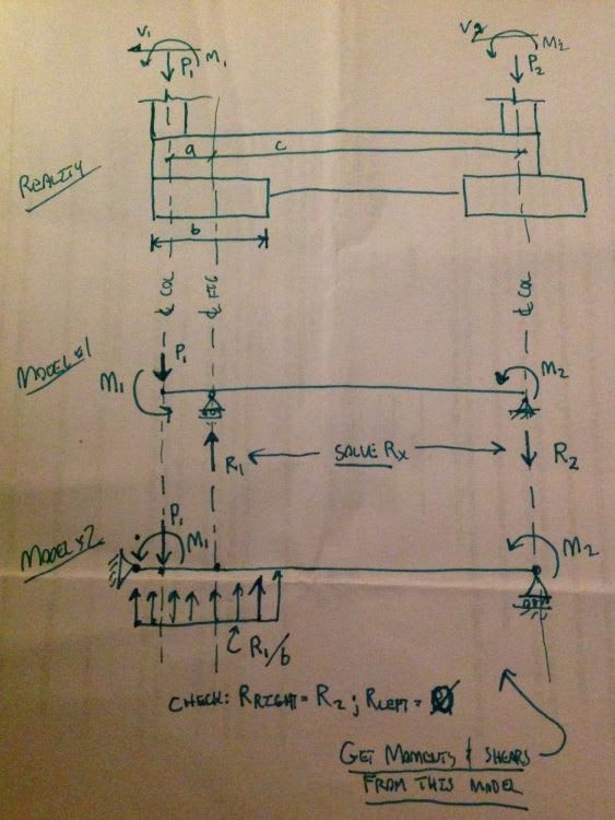
However, in reality the footing is essentially fixed to the strap beam and in a sense it is "fixed" to the soil - i.e. there are numerous soil "springs" supporting this footing so idealizing it as a pin isn't perfectly modeling reality.

With today's software (i.e. RISA Foundation) we can model this concrete configuration and when we do we get a significant gradient of soil stress under the footing closest to the property line.
In most cases, assuming a uniform soil stress results in an intuitively sized footing. But if we assume a soil-spring behavior, we get much larger soil stresses resulting in very large footings.

When a geotechnical engineer provides us with an allowable soil bearing pressure, it is assumed that this is generally for simply, uniformly loaded pad footings.

BUT.....

1. Soil isn't really linear is it? i.e. springs are only general approximations of soil behavior
2. Can the maximum pressure at the footing toe exceed the general allowable values a geotechnical engineer provides?
3. Thousands of strap type footings have been built in the past assuming uniform bearing - they seem to apparently work.
4. Does the soil somehow allow minimal rotation and still provide a general uniform bearing anyway...despite what our FEA foundation analysis suggests?

Thoughts and help please!


Check out Eng-Tips Forum's Policies here:
faq731-376
 
Replies continue below

Recommended for you

The stiffness of the strap beam plays a decent role. I've always been told stiffness of the beam should be 1.5 to 2x the stiffness of the foundation. operating under this rule of thumb I get pretty decently close the an idealized condition under the foundations.

From FEM:
Capture_pzyzxx.png


From Traditional Methods:
Capture_eyqqm2.png


1. agreed, the type of springs we're using in our FEM analysis are still approximations. usually takes a bit of back and forth with the Geotech to get the spring constant we use in an FEM mat analysis to align with their settlement numbers.

2. In my experience localized spots of higher design stress are allowed but usually situational and required us to specifically ask the geotech. Think the reality of it is there will be localized hot spots under all the foundations as the actual soil stiffness is likely to vary all over the job site.

3. with stiffer straps you get close, think some the non-linearity of the real structure comes into play in some force redistribution or perhaps you have a concrete foundation wall running continuous along the edge that instead of going along for the ride helps distribute some of the bearing more. Also the loads we are designing for aren't necessarily ever seen in the life of some structures.

4. I think the nature of the soil being spring like allows for the rotations to happen as spots compress and settle.

On the FEM side your also likely getting a lumped spring at the mesh nodes vs a continuous sponge so this itself can add some inherent eccentricity to the analysis depending on the quality of the mesh.

Open Source Structural Applications:
 
JAE...no it is not vertically linear. Soil stress spreads at approximately a 45 degree angle from the bottom of the footing. The more cohesive the soil, the more vertical that angle becomes. Bottom line...if a footing is placed next to another footing, there will be load influence on the soil below the existing footing.
 
Sweet. I do like to see one of my sketches pulling double duty.

JAE said:
2. Can the maximum pressure at the footing toe exceed the general allowable values a geotechnical engineer provides?

I believe so and feel that this is the key. Most of the time, the allowable bearing stress is not a value for which the earth gives way catastrophically but, rather, a pressure at which a certain, permissible settlement occurs. As such, if your soil stress is assumed linear then, in theory, you're settlement value at the center of the footing is the same as it would have been at the uniform, allowable pressure, even if you've over-stressed the soil at the peak. Technically, I guess that your settlement at the footing is greater than it is at the center of the footing due to the footing rotation but that value is usually small enough to be little more than noise compared to all the other sources of uncertainty at play.
 
I tend to take the simplistic approach here, just using the beam approach to determine the footing forces. Seems to me that due to the stiffness of the grade beam, Little beam rotation will be seen, generating little moments to the footings. Consequently, I would conside any moments to be onternal to rthe system, not external. Due to the minimal retat io n, I would design the soIL pressures as uniform.

Mike McCann, PE, SE (WA)


Allowable soil bearing pressure is meant to control settlement, not prevent ultimate failure. As the bearing pressure is exceeded, and the footing tries to rotate, the moment is thrown back into the strap beam. Thus, the system behaves as you originally intended.

DaveAtkins
 
JAE -

I think your post points out one of the inherent limitations in doing an elastic analysis on something that is definitely not elastic in reality. The results you get from an FEM or RISAFoundation analysis are certainly reasonable (IMO) and can be used for design. However, that doesn't mean that it's the most EFFICIENT way to do the design.

I kind of look at this as the difference between allowable stress design and ultimate strength design. Your moment can be limited by My (moment where extreme fiber begins to yield). However, the cross section can really continue taking load until you get to Mp (the moment at which the ENTIRE cross section has yielded).

Hence, I think your drawing shows what should be a more efficient way to design the strap footing.

That being said I would take two approaches.
1) Gravity only loads. Hopefully, in this case there is no M1 or V1 or they are very low. In that case, I really want to see relatively even soil pressure between footing 1 and footing 2. Meaning my concern is making an attempt to limit the potential for differential settlement.

2) The lateral cases where I'd be okay with having a lot more soil bearing on one side vs the other.
 
Celt83
What did you use for relative stiffness between soil and the concrete? Did you enter some type of soil subgrade modulus in your software?
We get a much larger variant across the footing where the eccentric column is...despite the strap beam.

Ron
I know that soil isn't linear...but we structural engineers assume so anyway because that simplifies our calculations and....what else can we do given limited soil stress-strain info? And given our software products (i.e. RISA Foundation and the like) that use a linear spring.

KootK
I thought you'd appreciate its use!

KootK, msquared48, DaveAtkins
Yes - your points about the soil stress gradient simply "averaging out" and the footing behaving as a pin make some sense...this is the root of my overall question.
The problem is that initially, based on our 90 kip column load, we just have a LOT of gradient. And our footings, to keep the footing tip overstress to the given maximum allowable results in HUGE footings, even with a full stap beam/footing extending back into the building.

We were going to contact our geotechnical engineer to get their take on the idea of exceeding the max. allowable pressure at the tip - and by how much.

JoshPlum
Appreciate your points - It is just interesting that for many years, and in many foundation text books, a uniform foundation pressure is presumed in all the examples (just like KootK did) but once we get an FEA product in our hands we see the actual gradient and wonder how to respond to that.....thinking how we might answer a lawyer's questions about "why did you design a footing with stress higher than the allowable?"

Check out Eng-Tips Forum's Policies here:
faq731-376
 
JAE:
that model had a 100 pci (Rz) area spring, also included 0.01 pci for the Rx, Ry components for stability. The area spring is also only defined under the footing areas not under the section of beam between the footings. Mesh size was also set to 0.5 ft.

Open Source Structural Applications:
 
[blue](DaveAtkins)[/blue]

Allowable soil bearing pressure is meant to control settlement, not prevent ultimate failure.

Granted, the larger a foundation becomes (in plan view) the more likely settlement is to control the design......but a pure bearing failure is possible for a good sized footing. There would be noticeable settlements prior to that.....but all this could be quite sudden.

[blue](JAE)[/blue]

We were going to contact our geotechnical engineer to get their take on the idea of exceeding the max. allowable pressure at the tip - and by how much.

Good luck. I've tried the same and couldn't get much relief. (With one or two exceptions.) The stiffer the soil is, the more likely they will ok it.
 
JAE:

reran it with a bunch of different spring values. The stiffer the soil the less uniform the pressure. The last one shows a result with doubling the edge zone springs to get some representation of coupling effect (ACI 336.2R-88)

Loads: 100kips (DL)
Columns: 12x24, f'c = 4ksi, fixed far pinned at foundation
strap: 30"x30", f'c = 3ksi
left ftg: 8' x 5.5' x 16" thick, f'c = 3ksi
right ftg: 7'x 7' x 16" thick, f'c = 3ksi

in all cases there is 0.001 pci springs in the x and y direction to avoid the program throwing a stability error and the area spring is only modeled under the footings. mesh size is 1 ft.

Capture_bhyg8e.png


Open Source Structural Applications:
 
JAE...

If needed, extend the critical footing down to better bearing...

Mike McCann, PE, SE (WA)


Status
Not open for further replies.

Part and Inventory Search

Sponsor