Continue to Site

Eng-Tips is the largest engineering community on the Internet

Intelligent Work Forums for Engineering Professionals

  • Congratulations cowski on being selected by the Eng-Tips community for having the most helpful posts in the forums last week. Way to Go!

Spreader Beam cable angles 2

Status
Not open for further replies.

WARose

Structural
Mar 17, 2011
5,594
Have been doing some lift/spreader beam designs lately.....and one thing has been bugging me (and not for the first time): the buckling value vs. cable angles in a lot of these papers.

The 2 primary papers I use are:

1. 'Distortion Buckling of Steel Beams' by: Essa & Kennedy. University of Alberta Department of Civil Engineering, April 1993'. (p.206-210)

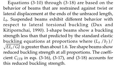
2. 'Buckling of Suspended I-Beams.', by: Dux & Kitipornchai, (1990). ASCE Journal of Structural Engineering,
116(7), 1877–1891

Ref #1 doesn't have anything with the hanging cables at a angle (just 90 degrees with the horizontal)......but Ref# 2 does. It gives the "nondimensional buckling load" based on several parameters....including the angle the cables are at. Looking at the figures in Ref.2, you get a great deal of variation based on that angle. And it's hard to always match your situation to the tables in that reference.

My suspicion is: the variation has to do with the imposed loading as much as anything. (I.e. the angle involved changes the major axis moment, axial load, etc, and that is accounted for.)

Reinforcing that suspicion is the following statement in Ref #2:

For all cable angles, the curves in Fig. 7 feature severe reductions in buckling
capacity as loads move even some small distance from the optimum
location. This highly sensitive reduction is due primarily to increases in the
extent and magnitude of major axis bending moment patterns. This, combined
with the relatively ineffective partial torsional restraints, causes the
reduction in buckling strength.
This feature of behavior should be borne in
mind by designers, as it is not usual for small alterations in loading configurations
to have such a significant effect.


So I guess what I am asking is, by Ref#1 (with all other things being equal and all cable attachments being nowhere near the shear center): can you figure one of these things with the cable angles at 90 degrees and be confident you are getting a strong axis buckling load that cannot be exceeded (with the proper SF)?

Granted, if you do so, you will need to superimpose other loads that this is not taking into account (i.e. axial, strong-axis, accidental weak axis, etc.). But I just want to be sure about a buckling load here.
 
Replies continue below

Recommended for you

Firstly, I don't have either of your references so know that I'm flying blind with respect to that.

WARose said:
can you figure one of these things with the cable angles at 90 degrees and be confident you are getting a strong axis buckling load that cannot be exceeded (with the proper SF)?

I'm inclined to say no. Cable angle will, as you've surmised, introduce an eccentric axial load into the system that would need to be combined with other load effects in order to evaluate the overall impact on stability. Given the non-conventional nature of the beam torsional restraints, I would expect that combination to be

a) complex owing to the interelated-ness of the various effects and;

b) not necessity captured by conventional AISC combined load check procedures.

Ref #2 said:
For all cable angles, the curves in Fig. 7 feature severe reductions in buckling capacity as loads move even some small distance from the optimum location.

I don't understand what is meant by "the optimum location". Can you elaborate?
 
Thanks for your input Kootk.

Given the non-conventional nature of the beam torsional restraints, I would expect that combination to be

a) complex owing to the interelated-ness of the various effects and;

b) not necessity captured by conventional AISC combined load check procedures.

You've captured the essence of what I am wondering about: is it the loads.....or do the cables provide some restraint at one angle they do not provide at another? They provide no restraint (and the whole thing is unstable) if the load and the suspended cables are at the same height. (I.e. free to rotate.)

But then again....they make it sound like the impact is minimal (past a certain point; reminds you of Appendix 6 in AISC).

I don't understand what is meant by "the optimum location". Can you elaborate?

The paper puts it this way: Loading at this point almost removes major axis bending from the beam between cable attachment positions.

You'd have to see the layout of Figure 7 to get what they mean.
 
WARose said:
Thanks for your input Kootk.

No problem. You've amassed a respectable goodwill trade surplus with the international bank of KootK.

WARose said:
or do the cables provide some restraint at one angle they do not provide at another?

I vote no. I see the only LTB restraint being that provided by the elevation difference between the points of load application and the points of support. I struggle to see how that could be meaningfully affected by cable angle.

WARose said:
Loading at this point almost removes major axis bending from the beam between cable attachment positions.

So this optimum location business is about how much of the beam cantilevers beyond the support points?

WARose said:
You'd have to see the layout of Figure 7 to get what they mean.

With the appropriate motivation, I feel as though you could help me out with that.
 
I vote no. I see the only LTB restraint being that provided by the elevation difference between the points of load application and the points of support. I struggle to see how that could be meaningfully affected by cable angle.

Ok....that's what I think too.

So this optimum location business is about how much of the beam cantilevers beyond the support points?

The spreader beam in Fig.7 doesn't have the support cables come to the ends......just some distance from it....and yes it does leave it with a cantilever.

 
Noted. What is the particular geometry of your beam with respect to cantilevers and cable angles?
 
KootK said:
WARose said:
or do the cables provide some restraint at one angle they do not provide at another?

I vote no. I see the only LTB restraint being that provided by the elevation difference between the points of load application and the points of support. I struggle to see how that could be meaningfully affected by cable angle.

Agreed. As such, the buckling capacity determined is independent of cable angle. Only the demands to the compression flange (axial, major axis bending due to eccentricity) change. I don't understand why all the academics try so hard to work this into a single closed form answer rather than just handling it on a combined stress basis.

KootK said:
WARose said:
Loading at this point almost removes major axis bending from the beam between cable attachment positions.

So this optimum location business is about how much of the beam cantilevers beyond the support points?

Right -- for a "uniformly loaded" spreader beam with lots of rigging coming down (e.g. picking something really flexible) or for a rigging application where the "spreader beam" is the load (e.g. picking a steel girder), there's a lot of research about the optimum location to pick the load/spreader. Hint: It's essentially the quarter points.

Also, don't forget Helwig's research for buckling of suspended beams. It's always felt a little aggressive to me, but it's a lot easier to apply to various situations than Kitipornchai's paper.


----
The name is a long story -- just call me Lo.
 
Half-baked thought right before bed; will have to revisit this in the morning.

Edit: fixed!

KootK said:
I see the only LTB restraint being that provided by the elevation difference between the points of load application and the points of support. I struggle to see how that could be meaningfully affected by cable angle.

The torsional restraint against buckling is provided by the elevation difference. It reasons that as the cable angle gets closer to horizontal the load on the spreader beam from the cables creates a rapidly increasing horizontal component. If all the cables in the system are in the same plane this can cause P-delta flexural forces in the spreader beam while simultaneously reducing the available vertical force providing the torsional resistance.
Code:
NO! Sum of the forces to zero you moron!
In addition; the increased axial force on the spreader beam will increase the compression forces in the flange resulting in increased buckling effects.

Like KootK, I have neither reference unless it's buried in my digital library from whenever the last time I designed a spreader beam.

Ian Riley, PE, SE
Professional Engineer (ME, NH, VT, CT, MA, FL) Structural Engineer (IL)
American Concrete Industries
 
For shallower rigging angles, the axial forces (and potential for P-delta) in the spreader do increase.

But the vertical force in the rigging has to stay constant -- it's a function of the suspended load.


----
The name is a long story -- just call me Lo.
 
Lom said:
But the vertical force in the rigging has to stay constant -- it's a function of the suspended load.

Doh! You're entirely correct; like I said, half-baked thought.

Don't drink and derive! :p

Ian Riley, PE, SE
Professional Engineer (ME, NH, VT, CT, MA, FL) Structural Engineer (IL)
American Concrete Industries
 
WARose said:
So I guess what I am asking is, by Ref#1 (with all other things being equal and all cable attachments being nowhere near the shear center): can you figure one of these things with the cable angles at 90 degrees and be confident you are getting a strong axis buckling load that cannot be exceeded (with the proper SF)? Granted, if you do so, you will need to superimpose other loads that this is not taking into account (i.e. axial, strong-axis, accidental weak axis, etc.). But I just want to be sure about a buckling load here.

Strictly speaking, I would have to vote no. Here's what I've got:

1) Stating the obvious, the only thing that keeps this from being a straight forward, combined stresses, AISC beam-column design is the fact that our LTB end restraints are horrendous, non-linear springs rather than sexy, rigid-ish things. Boo.

2) There are at least three sources of strong axis bending moment and therefore at least three sources of LTB potential. And each one of them needs to be dealt with in a way that accounts for the spongy LTB restraint just mentioned. Tackling each source in turn:

2a) Primary bending due to transverse loading. Using the charts for the 90 degree situation covers this. Check.

2b) P-baby-delta for the axial load acting on the shape displaced by strong axis bending. For most practical cases with loads close to the optimal location and Ix >> Iy, I'm willing to call this effect negligible.

2c) Primary bending due to the eccentrically applied axial load. This is the one part where I believe that your proposal falls short in that, for this moment, the effect of the spongy LTB restraints is not accounted for.

I suspect that your method could be successfully -- and easily -- tweaked by generating an intelligent, faux moment diagram that combines the effects of 2a & 2c. If you want to get into that, though, I'll need to know a bit more about the particular geometry that your considering. Obviously, there'll be a pretty big difference between loads inside the cables and loads outside the cables etc.
 
To add to kootk's list - another source of strong axis bending is the self-weight of the beam. Not significant for lifting beams where the lifted load induces a lot of bending in the beam, but I've found that for long spreader bars, the self-weight moment and initial deflection can have a significant impact on the load rating of the bar.

I see lots of references to various papers, but what about ASME BTH-1? I didn't take a close look to see if it directly addresses the issues noted above, but I think if you're designing lifting beams and spreader bars, this document should at the top of the pile of references.
 
In the BTH-1-2014, they added a Cltb factor to reduce the allowable bending stress and it reads as shown below (note that this is for doubly symmetric beams, also note that eqn 3-17 is for Lb > Lr):
Cltb_t1w36z.jpg


IMO, it's better to keep the rigging at the end, make the beam bigger (i.e., less efficient), use rigging angles above 45 degrees, and go home and sleep at night. If it's a one-off, you can usually sell the user on the feel-good factor. If it's a multi-use (like in a factory), then I'd sell the it's-likely-to-not-get-used-correctly-every-time angle.


BTW, here's the BTH commentary on the Cltb factor:
Cltb_Comm_prp958.jpg
 
[blue](Kootk)[/blue]

2c) Primary bending due to the eccentrically applied axial load. This is the one part where I believe that your proposal falls short in that, for this moment, the effect of the spongy LTB restraints is not accounted for.

Even if that primary bending moment was compared to the buckling load from Ref#1? What I was proposing was comparing all strong-axis moments developed to this value. of course that goes back to how "spongy" are the supports in Ref#1 (compared to Ref#2).

It appears I may be stuck with Ref#2 one way or the other.

 
WARose said:
Even if that primary bending moment was compared to the buckling load from Ref#1?

Maybe?? Can you elaborate on how you're using reference one? Is it equation 7.10 and figure 7.7? If any of this information is known, it would really help me to know the arrangement of the the loads and supports for the situation(s) that you're evaluating.

 
I've always just used your reference 2, or preferably used closed sections as lifting beams. I find it's more efficient in terms of weight and brainpower expended, at the cost of some knife plate connections.
 
[blue](Kootk)[/blue]

Maybe?? Can you elaborate on how you're using reference one? Is it equation 7.10 and figure 7.7? If any of this information is known, it would really help me to know the arrangement of the the loads and supports for the situation(s) that you're evaluating.

Yep. Comparing the values you come out with in Ref#1.....they aren't that much different than Ref#2. But Ref #1 lets you calculate exact values in many cases. (I.e. the "nondimensional buckling load" parameter.) Ref#2 has you reading it off of graphs. But the calculation methods in Ref#1 doesn't include the angle parameter. (It also has the attachment at the top flange, which (as per Figure #8 in Ref#2) could slightly underestimate the buckling value....which is ok.)

So it's a case where you've got one that let's you calc the exact value.....but only for a generic case vs. the other that has all sorts of conditions, but forces you to interpolate off of charts.
 
So you're running the eccentric axial load through the reference one methodology built for transverse loads? If so, that part gives me pause due to the differing moment patterns unless you've devised a way to do this:

WARose said:
I suspect that your method could be successfully -- and easily -- tweaked by generating an intelligent, faux moment diagram that combines the effects of 2a & 2c.

 
[blue](Kootk)[/blue]

So you're running the eccentric axial load through the reference one methodology built for transverse loads? If so, that part gives me pause due to the differing moment patterns....

That's a good point: it's a Cb=1.14 in one vs. Cb=1 for the other.
 
Status
Not open for further replies.

Part and Inventory Search

Sponsor