Cantilever Canopy Seems ok....can anyone confirm?
(OP)
So Im attaching a cantilever canopy I'm running. It seems to good to be true and I was wondering whether anyone might look at it and give me some pointers. The canopy only extends (cantilevers) 5 ft and is attached to a masonry wall that has vertical reinforced concrete fill every 32 inches on center. I was hoping the architect would want aluminum but he put it on us to do with steel. Im using a channel against the masonry wall (2 A325 bolts @ 32"O.C.) and Wide Flange beams extending 5 ft. @ 5 ft. O.C. and standing seam panel over them. Any help is appreciated.
Thanks!
ps. I tried using pin connection for the beam connectors and always got instabilities at every cantilevered joint. I figures I'd allow the moment at the connecting end instead (Weld, is this the best approach?
Thanks!
ps. I tried using pin connection for the beam connectors and always got instabilities at every cantilevered joint. I figures I'd allow the moment at the connecting end instead (Weld, is this the best approach?
RE: Cantilever Canopy Seems ok....can anyone confirm?
2) You're using LRFD load combinations. However, the design code (on the Codes tab of the Global-Model Settings) is set to ASD.
3) You've got boundary conditions at the base of every one of your cantilevers. Therefore, your channel will not be taking ANY loading other than it's self weight.
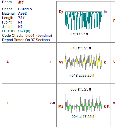
4) Your channel isn't going to be 73ft long in reality. If I were you I'd break it up into smaller pieces. That way, the moment, shear and torsion diagrams RISA gives you for each member will have a bit more granularity.... Meaning the program only uses a certain number of data points (approximately 100 for your file) when plotting these diagrams. That way you will not longer have diagrams that look like this:
I hope that helped!
Josh
RE: Cantilever Canopy Seems ok....can anyone confirm?
@jayrod12 Thanks for reading.
RE: Cantilever Canopy Seems ok....can anyone confirm?
It's a little confusing at first. But, when you create the area load, the 1st node is A, the 2nd is B, 3rd is, and the 4th is B. Within this context, the B-C direction means the distribution direction is parallel to a line that connects nodes B and C. That would make the distribution direction perpendicular to your cantilevers. Just like if you had metal deck spanning in that direction. You'll even get a little arrow in the model view showing you the distribution direction.
The problem with using plates is that they have stiffness and you'll get more of a two way distribution than the 1-way distribution you probably wanted. If a two way distribution is what you want, you could still use member area loads (with a distribution direction of "Two Way"). If you're really keen on using plates to model a concrete deck or something then go ahead. But, I would mesh it pretty good. I try to us a minimum of 3 plate between points of inflection. So, I'd say something like 7 plate between each cantilever.
RE: Cantilever Canopy Seems ok....can anyone confirm?
@oldrunner, thanks for the recommendation. I have used A325 bolts up to 7 inches. However, for every inch after a factor on diameter you loose a percentage of its capacity by AISC. I don't remember the factor but it is considerable when using up to 7 inches. To be honest I'm not very comfortable with the plate on the other side either. I feel like once the tension capacity on the concrete is met that canopy still goes out, but I do suppose it is a lot safer. However, I'm not comfortable relying on the concrete anchor alone for a cantilevered member but everyone here calls me a rookie for insisting on adding supports on the other end even if at large on center spacing.