I have a question about a pressure transducer reading that doesn't make any sense. I have a Pressure sensor soaked in water at 125c and 11,000 psi for 24 hours (See images). When bleed off, gauge pressure is 1,000 psi less than sensor pressure. Is there any way that atmospheric pressure cold be reduced enough to give a 600-1000 psi offset pressure that is greater than actual reference gauge pressure? Even if atm. chambers bled to full vacuum how could 14.7 psi increase in sensor pressure from say 5,000 psi to 5,014.7 psi yield a 1,000 psi difference with sensor pressure? Outgassing would create opposite problem as pressure in chamber would increase. Pics of Test Hoohup sketch and cross section of gauge with sensor mounted are attached. I am new to working with electrical components and am learning as I go...
There was a Doe Corning Dieleectric gel applied to wire bonds that is in a gelatin state. Don't see what is can do its so non-viscous and shows no signs of curing.
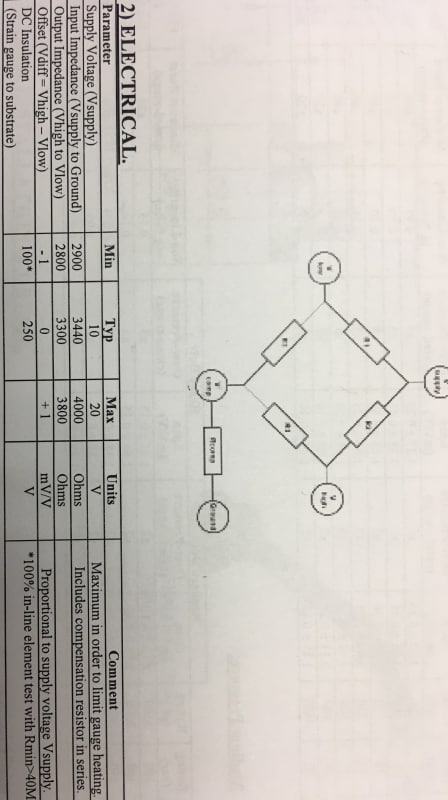
Sensor Span 2.7V mV/V +/- .2
Vsupply : 10V
Wheatstone bridge mounted on diaphragm of transducer.
Sensor Over pressure is 20,000 psi
Sensor Burst pressure is 58,000 psi
Sensor Rating: 10,000 psi (we exceed rating to serve as safety factor check for gauge and sensor)
y=370x
Ouput V P (psi)
1 370.3703704
5 1851.9
10 3703.703704
15 5555.555556
20 7407.407407
25 9259.259259
27 10000
Any thoughts would be much appreciated. Thanks
There was a Doe Corning Dieleectric gel applied to wire bonds that is in a gelatin state. Don't see what is can do its so non-viscous and shows no signs of curing.
Sensor Span 2.7V mV/V +/- .2
Vsupply : 10V
Wheatstone bridge mounted on diaphragm of transducer.
Sensor Over pressure is 20,000 psi
Sensor Burst pressure is 58,000 psi
Sensor Rating: 10,000 psi (we exceed rating to serve as safety factor check for gauge and sensor)
y=370x
Ouput V P (psi)
1 370.3703704
5 1851.9
10 3703.703704
15 5555.555556
20 7407.407407
25 9259.259259
27 10000
Any thoughts would be much appreciated. Thanks
")