Continue to Site

Eng-Tips is the largest engineering community on the Internet

Intelligent Work Forums for Engineering Professionals

  • Congratulations KootK on being selected by the Eng-Tips community for having the most helpful posts in the forums last week. Way to Go!

vehicle rating of slab on drilled piers

Status
Not open for further replies.

delagina

Structural
Sep 18, 2010
1,008
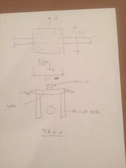
I'm designing a slab approx. 20'x20' supported by drilled piers.
This is to protect the pipe underneath.
This is a private slab/road and vehicles passing are pick up trucks.
I want to keep this calculation simple and not do any moving loads.
I can design the slab easily with static point load, run it a few times with different point loads location that I think are the critical locations.

1) I am not sure though what static point load to use per vehicle rating or vice versa. Is there a guide to this?
Client wants a vehicle rating for the slab.

2) client wants this slab removable. I guess to service the pipe in the future.
Can someone link a vendor for a lifting eye that I can use that will not protrude so it wont get hit by vehicles.

3) if slab is removable then it is just bearing on top of drilled pier. only the friction on top of pier and soil passive pressure will prevent it from moving.
will that be enough, I imagine there aren't much horizontal force here?


Untitled_a1xucz.jpg
 
Replies continue below

Recommended for you

Agreed -- there's no need for moving load analysis if you select a few static cases carefully.

Without additional guidance from the client, I'd probably size the slab either for at least an HS15 truck (maybe an HS20 depending on how private the road really is), or the minimum design load from your region's culvert specifications. Those are all bigger than pickup trucks, but it's really tough to control loads on something like this.

To give you a few reference points on horizontal load, AASHTO prescribes 25% of vehicle weight as braking force (6' above surface). For material delivery on construction sites, ASCE 37 recommends 20% of the vehicle weight (at the surface). So not insignificant -- but you can probably take it all in friction if you have a decent prepared subgrade under the slab.

Depending on what the surrounding road is (I'm guessing dirt), I'd probably want to provide some sort of sleeper slab for long-term durability. Otherwise your adjacent road may subside and cause a big jolt as trucks step onto this slab. (This would be a controlling case for horizontal load)

Speaking of which, I'd apply an impact load to your slab regardless. For uncontrolled traffic, say 33%. If it's a controlled site, you might get away with less.

As for lifting eyes -- I'd talk to a local precaster if you haven't already.

----
The name is a long story -- just call me Lo.
 
There is another way to look at this:

A cast-in-place, flat slab highway bridge with a 20' span is going to be at least 16" thick. This is with full support on two sides (the bridge substructure), not just the four points specified (the drill piers at the corners). Unless you use a sophisticated a piled raft design, best to disregard any support or horizontal load resistance from the subgrade (just a little subgrade settlement and the drill piers have 100% of the load).

Even a 20' x 20' x 16" slab is going to weight about 80 kips. Depending on how the pickup points are located on the slab, designing for lifting may be the controlling factor... not the vehicle load.

[idea]
[r2d2]
 
Ah, good point about subgrade settlement. I missed that.

----
The name is a long story -- just call me Lo.
 
delagina said:
1) I am not sure though what static point load to use per vehicle rating or vice versa. Is there a guide to this?
Client wants a vehicle rating for the slab.

None that I'm aware of. I'd check key locations like center of the slab, centered between two piers, and just adjacent to a pier (for max punching shear). I can almost guarantee that the tandem axle load will control over the HS-20 vehicle load and it's probably more realistic to the vehicles that might be driving around.

delagina said:
2) client wants this slab removable. I guess to service the pipe in the future.
Can someone link a vendor for a lifting eye that I can use that will not protrude so it wont get hit by vehicles.

20'x20', I'm going to guess 16" thick as well, probably closer to 18" as an optimal thickness to keep rebar sizes down. As SRE noted this is a 80,000 lb slab at a minimum, lifting design to avoid cracking will be just as important as vehicle loading.

ALP Lifting Pins are what we use for our heavy lift items. [URL unfurl="true"]https://www.patterson-online.com/CatSearch/296/alpt-lifting-pin-anchor-system[/url] They require a special "zipper" attachments to grab them, most precasters have these attachments but it might be a hassle for the owner to need to rent/buy them when they need to remove the cover. Picking up this slab will be no small task. I'd personally recommend beams between the piers with precast planks spanning between then. This way it wont require as large of a crane to remove panels and the planks/beam can be precast and set with a boom truck greatly reducing the cost of the project.

delagina said:
3) if slab is removable then it is just bearing on top of drilled pier. only the friction on top of pier and soil passive pressure will prevent it from moving.
will that be enough, I imagine there aren't much horizontal force here?

For an 80,000 lb slab that's not likely to move under normal vehicle conditions. I'd suggest rubber bearing pads between the slab and piers, otherwise the corners of the pier tops will likely spall off and it will ensure a more uniform contact while still being removable. However, you definitely need to design the piers to take this lateral load from friction. As SRE notes, a pair of piers will likely see 100% of this lateral load before the load migrates to less stiff resistances.

Professional Engineer (ME, NH, MA) Structural Engineer (IL)
American Concrete Industries
 
Why don't you replace the drilled piers with vertical reinforced walls to provide full bearing of the slab on two sides rather than being supported at 4 points only. This shall result in more bearing area for the slab and extra connection points to design the lifting rugs as suggested above. This option shall be compared with your drilled pier design for cost and constructability comparison since we am not aware of the pipe depth.
 
Drilled pier would be easier to design and easier in construction in my opinion. The "wall footing" may be more work.
 
If this is for a private road, I would design it for HS-20 so that you would have all of your bases covered.

This would allow for a fully loaded moving truck (not the truck physically "moving" across the bridge, but the type of truck that contains all of your belongings when you "move" from one residence to another)
 
Dont forget local fire dept, can/will they need to cross it anytime?
 
Check what your local fire department requires to go across the what ever span you end up with. It may be greater than a H20 truck. I like the idea of retaining wall/box combined with a ground level track to slide the slab on. Maybe have rail or guides. Use a winch to move the slab back and forth. Takes some planning but lot cheaper. For trucks across the slab post either a 5 or 10 mph.
 
@lomarandil, can you clarify more about sleeper slab detail?
 
Tehmightyengineer,

I will do per your suggestion and add beams between piers and use precast planks for the slab.
Do you have a suggested plank for this case? Will these planks just bear on top of the beam?
It needs to be removable but at the same time resist the worst horizontal force from vehicles.
I'm a bit confused how to connect this planks to the beams.
 
Status
Not open for further replies.

Part and Inventory Search

Sponsor