×
INTELLIGENT WORK FORUMS
FOR ENGINEERING PROFESSIONALS

Contact US

Log In

Come Join Us!

Are you an
Engineering professional?
Join Eng-Tips Forums!
  • Talk With Other Members
  • Be Notified Of Responses
    To Your Posts
  • Keyword Search
  • One-Click Access To Your
    Favorite Forums
  • Automated Signatures
    On Your Posts
  • Best Of All, It's Free!

*Eng-Tips's functionality depends on members receiving e-mail. By joining you are opting in to receive e-mail.

Posting Guidelines

Promoting, selling, recruiting, coursework and thesis posting is forbidden.

Students Click Here

Molded Linkage
3

Molded Linkage

Molded Linkage

(OP)
Hey Guys,

Not sure if this is the best forum to ask this question but if you can give me a few tips it would be awesome.

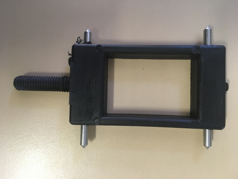
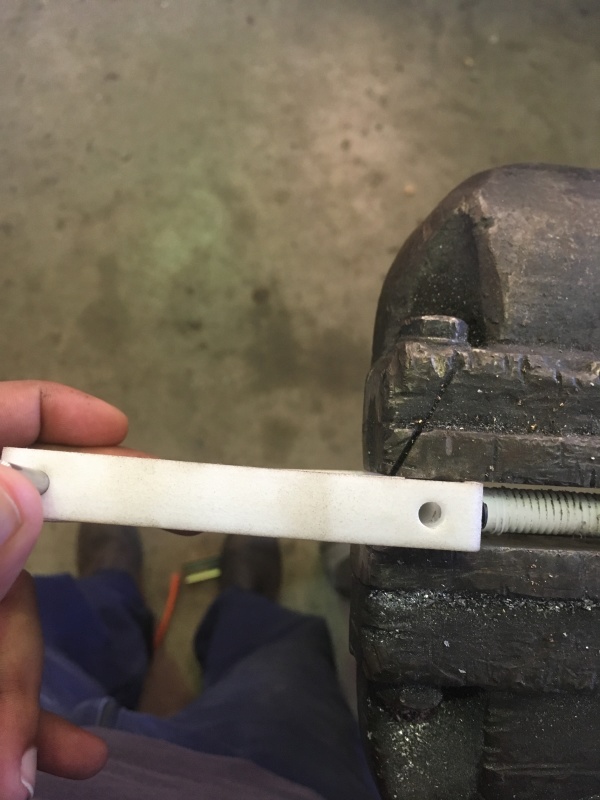
So below is the original linkage part we used which was made out of glass filled nylon. Very rigid and works like a treat but uses a lot of material and takes long to cool because its solid.


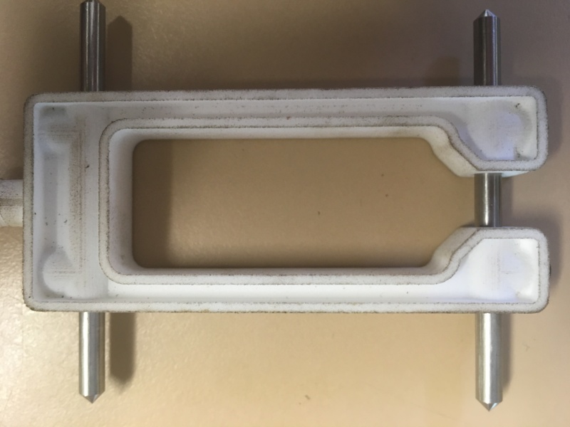
So I've been working on a 3D printed prototype (SLS Nylon) where I narrowed it down by 10mm, cut the center off in one end, and used thin wall sections.


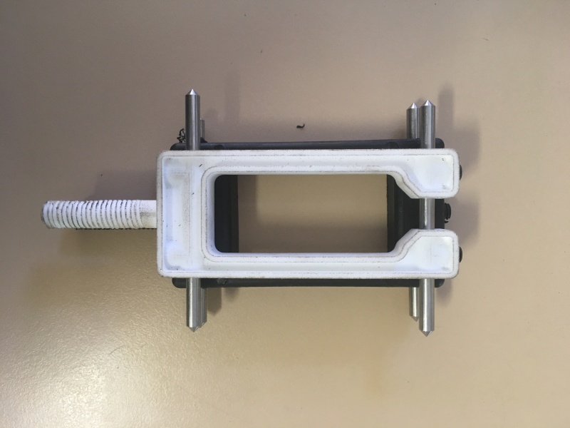
Please see comparison


Problem with the new one is it tends to twist in the centre more than I like compared to the old one.


I do understand the Glass filled Nylon would be a bit stiffer than the 3D printed stuff. But I still feel it won't be strong enough for the job.

Does anyone have any tips on how best to add ribs etc to stiffen the new part while still using less material?

Do you reckon taking the center part off one end on the new one is contributing to the twisting?

Anything else you can advice me to try?

Cheers

Roshane

RE: Molded Linkage

You have reduced the bending resistance by making the solid pieces into "I" sections.

You also reduced the width so there is less leverage from the material that remains.

The ABS is not glass filled, so the stiffness is lower.

Removing material away from the bending plane makes it easier to bend the item. Making the perimeter of a section less continuous makes an item easier to bend.

RE: Molded Linkage

Quote:

and takes long to cool because its solid.

The cycle time for an injection molding machine is hundreds of times faster than a 3D print, so I'm not seeing the point of the exercise.

If you molded a part in the shape you have 3D sintered, it would also be more flexible and lighter than the more primitive part, and probably a good bit stronger than the printed part too, because 3D printing doesn't typically get real close to full material density.

<tangent>
My favorite molder made some amazing parts in glass/ ptfe filled Delrin. My first sketches had a lot of relieved areas/ I sections, but Siggy liked his molds simple. He molded the parts with flat surfaces, large cross sections, and deep sink marks, i.e. cavities, on the _inside_.
</tangent>

You should be talking to your molder about improvements to your parts.

Mike Halloran
Pembroke Pines, FL, USA

RE: Molded Linkage

(OP)
Hi Guys

Thanks for the replies.

Quote (MikeHalloran)


We 3D Printed the new model to make sure all the dimensions were okay to create a new mold and also to see where we could save material.

The parts we were getting were from a mold that was over 30 years old and was flogged out.

Yes I'll be talking to my molder but I came here for a second opinion and fresh new ideas to get the best result smile

Quote (3DDave)


Thanks those tips helped me figure out why it was behaving the way it did.

Do you think the best option is to join the I sections like the old one and then use thin walls like the new one and see where it ends up?

Cheers

RE: Molded Linkage

To partially answer your questions:
Removing the center from the distal end will introduce a new distortion, where the cantilevered half-ends will curl toward each other, or out of plane, during cooling after ejection from the mold. Depending on the mating parts, you may not be happy with that result. One way to deal with that is to fixture the parts for post-cooling, e.g. by inserting a simple wood block in the 'U' and securing it with a rubber band until the parts are near room temperature. The molder will probably think of something like this if your tolerances suggest a need to do so.

Lightening the part by converting a solid rectangular section to an I section will probably allow shorter injection cycles and reduce weight and material use, but it also reduces the section properties, so the part will be less resistant to twisting as you demonstrate with the printed part. You can improve stiffness in that mode with diagonal ribs, but you won't regain the torsional stiffness of the current design. Bigger radii in the internal corners may help, mating parts permitting.

IF the current design is molded in nearly neat nylon, you can get back some of the stiffness by using glass-filled nylon. I have found the practical limit is somewhere near 33 pct glass fiber. Note that the glass reinforced nylon is more abrasive than neat nylon, so mold life will suffer somewhat, e.g. 5 years vs. 30 years, guesstimated. Note that heavily glass-filled parts will have a distinctly grainy surface even where the mold is glossy.


Mike Halloran
Pembroke Pines, FL, USA

RE: Molded Linkage

Any particular reason the center needs to have that big hole? How about turning the whole thing into a diagonals truss block?

Something like:


Also I believe you can use filled nylon in a 3D printer for a bit more real feel. You would want to use steel nozzles instead of brass.

Keith Cress
kcress - http://www.flaminsystems.com

RE: Molded Linkage

3
You might want to 3D print the old version so you can compare the effects of the design independent of the material/processing differences.

RE: Molded Linkage

(OP)

Quote (MikeHalloran)


Thanks for those tips. The reason I cut away the centre from the distal end was to hopefully save a bit of material and to aid faster cooling times. But since that's worked against the stiffness of the part, what I've decided to do is make it to the external shape as the old one, beef the I beams joining the two ends up from 7mm to 10mm and see how we go. I'm still saving about about 20% on material which is pretty good.

Quote (itsmoked)


The centre has to be hollow to allow another part to pass through although the hole can be made smaller.

Quote (John2025)


Yes the plan is to make a 3D printed part the same as the old one but with hollow walls to see if that is a good compromise.

Any other tips would be greatly appreciated.

Red Flag This Post

Please let us know here why this post is inappropriate. Reasons such as off-topic, duplicates, flames, illegal, vulgar, or students posting their homework.

Red Flag Submitted

Thank you for helping keep Eng-Tips Forums free from inappropriate posts.
The Eng-Tips staff will check this out and take appropriate action.

Reply To This Thread

Posting in the Eng-Tips forums is a member-only feature.

Click Here to join Eng-Tips and talk with other members! Already a Member? Login


Resources

Low-Volume Rapid Injection Molding With 3D Printed Molds
Learn methods and guidelines for using stereolithography (SLA) 3D printed molds in the injection molding process to lower costs and lead time. Discover how this hybrid manufacturing process enables on-demand mold fabrication to quickly produce small batches of thermoplastic parts. Download Now
Design for Additive Manufacturing (DfAM)
Examine how the principles of DfAM upend many of the long-standing rules around manufacturability - allowing engineers and designers to place a part’s function at the center of their design considerations. Download Now
Taking Control of Engineering Documents
This ebook covers tips for creating and managing workflows, security best practices and protection of intellectual property, Cloud vs. on-premise software solutions, CAD file management, compliance, and more. Download Now

Close Box

Join Eng-Tips® Today!

Join your peers on the Internet's largest technical engineering professional community.
It's easy to join and it's free.

Here's Why Members Love Eng-Tips Forums:

Register now while it's still free!

Already a member? Close this window and log in.

Join Us             Close