×
INTELLIGENT WORK FORUMS
FOR ENGINEERING PROFESSIONALS

Log In

Come Join Us!

Are you an
Engineering professional?
Join Eng-Tips Forums!
  • Talk With Other Members
  • Be Notified Of Responses
    To Your Posts
  • Keyword Search
  • One-Click Access To Your
    Favorite Forums
  • Automated Signatures
    On Your Posts
  • Best Of All, It's Free!

*Eng-Tips's functionality depends on members receiving e-mail. By joining you are opting in to receive e-mail.

Posting Guidelines

Promoting, selling, recruiting, coursework and thesis posting is forbidden.

Students Click Here

Post Tensioning Cable Slope
2

Post Tensioning Cable Slope

Post Tensioning Cable Slope

(OP)
Hi all!

I've searched far and wide but haven't been able to find this information: how does one calculate the slopes of PT cable knowing the locations of the inverts?

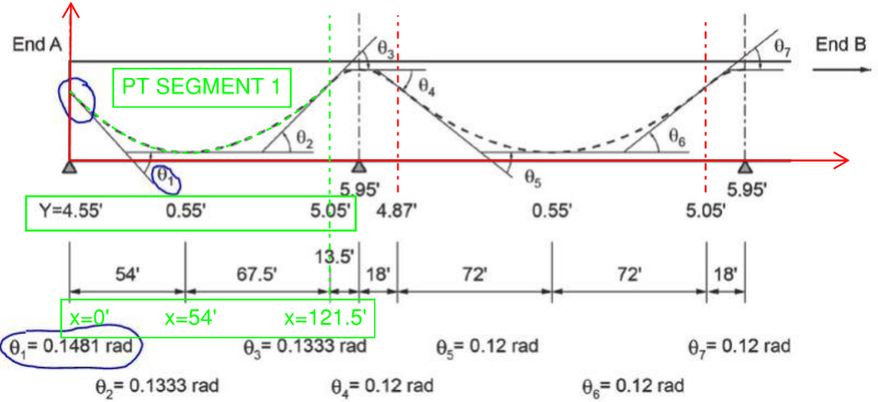
The below is an example from a US DoT guide. It shows that they have found the values of theta, but they have not shown how.
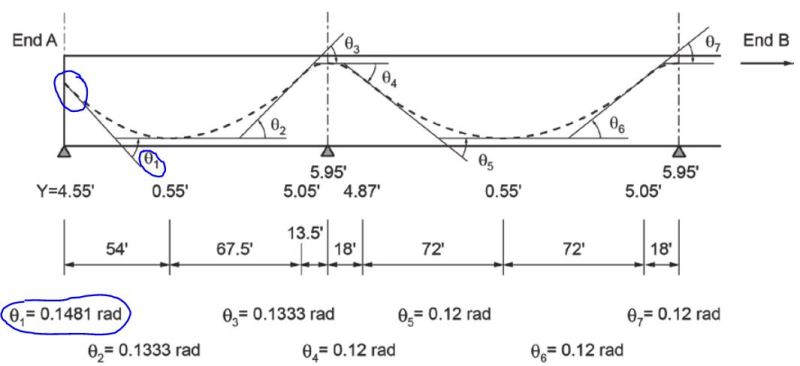


I've looked at using equations for catenaries, but they require knowing the tension and/or weight of the cable which in this case is completely irrelevant as in the field, the cable (or rather, duct) will be supported by whatever means required to achieve the needed drape. Without this information it seems one is required to solve equations with imaginary numbers and inverse hyperbolic equations with multiple unknowns (ain't nobody got time for that).

I know there is software which solves this (e.g. RAPT). However, I want to implement this in excel or Mathcad and hence would be happy with a reasonably accurate approximation.

No references I've seen on PT design seem to cover this point. Is this just common knowledge like a²+b²=c² and I have just neglected to pick it up throughout my education and career?

Any ideas would be greatly appreciated.

Replies continue below

Recommended for you

RE: Post Tensioning Cable Slope

You would need to know the curve type they have assumed.

presumably parabolic for the main parabola. Others used to suggest circular for the reverse curve over supports, but with a parabolic main curve, we found the solution for the reverse curve as a parabola was best to generate the math for. So we use parabolic for both.

So you need a parabola formula (y = ax^2 + bx + c) that results in their nominated slope at the transition point. They have defined the horizontal location of the transition points for you.

Or you use RAPTs curve and adjust the reverse curve radius to get their nominated slope at the transition point.

RE: Post Tensioning Cable Slope

VitoPito,

I agree with rapt - you need to know (assume?) the profile type - typically parabolic, but occasionally compound circular, and at the anchorage ends there is a straight 'tangent length' that can screw up things.

Before I started using rapt's RAPT software I used to do it manually, for building structures. I assumed a parabolic profile, and knowing three other profile points (left-end, low point, right-end), solve for three equations and three unknowns of y=Ax2 + Bx + C. Then differentiate the equation to determine dy/dx equation (hence slope) and plug in X value to obtain slopes at any point for that parabolic segment. Repeat for each segment of each drape. Lends itself to automation via spreadsheet or other.


For your stated example, taking the first span (the one I colored GREEN) adopt an origin, assume parabolic profile, and select the three points that define the profile, so the three (X,Y) points would be:

(0,4.55), (54,0.55) and (121.5,5.05)

If you do the 'plug and chug' you end up with:

y = 0.001158x2 - 0.136635x + 4.55 and slope: dy/dx = 0.002317x - 0.136625

If you input x=54 for dy/dx you should get 0.0 (zero slope, or minima, or low point), but you do not!. So, the ordinates/abscissa of the profiles are not a singular parabolic profile. For a singular parabolic profile, the low point would be at x=58.97' (setting dy/dy equation to zero and solve for x).

Inputting x=0 for dy/dx = 0.1366 rad (compared to the stated value of Θ1 = 0.1481).

Similarly, for x = 121.5, dy/dx = 0.1448 rad (compared to stated value of Θ2 = 0.1333).

The differences are explained that the example profile is a COMPOUND parabolic profile, not a singular one over the 121.5'.

What some bridge DoT do is break up the span segment into two separate parabolas over the 121.5' distance. One from 0 to 54, and the other from 54 to 121.5'. So both parabolas meet at x=54' with a slope of zero. Something like this, using the same example, and same origin:

So for part A parabola of span 1 the values of x, y and dy/dx for the known parameters are:

(0,4.55,unknown?) and (54,0.55,0.000)

So 'plugging and chugging': y = 0.001372x2 - 0.1481x + 4.55 and dy/dx = 0.002743x -0.1481

So for part B parabola of span 1 the values of x, y and dy/dx for the known parameters are:

(54,0.55,0.0000) and (121.5,5.05,unknown)

So 'plugging and chugging': y = 0.000988x2 -0.10666x + 3.43 and dy/dx = 0.001975x -0.10666

So if you input respective X values for each half parabola:

Θ1 = 0.1481, Θ2 = 0.1333 and at X=54' Θ1 = 0.000 and all matching the example values.


FYI - the reverse/inverted profile length over the supports is 10% of the span - hence the 13.5' and 18' distances in your example. The 54' dimension to the low point of the end span is 40% of the 135' span. Typically inflection point values.


I am curious, what is your reference for this example - which US DoT did you get the PT profle from, CalTrans, Florida DoT?

RE: Post Tensioning Cable Slope

I did not look at the end profile at the left anchorage.

This is not logical for multi-strand tendons.

For a start, the tendon will not stop at the centre of the support, it will extend a significant length past the support, probably at least 1 - 3' depending on the overall concrete details.

Secondly, to have the anchorages at a slope at the end is possible but not logical. Normally the tendons will be horizontal at the ends to enable standard stressing recesses to be used. Otherwise a stressing recess with a complicated shape will need to be manufactured to suit the angle of the anchorage. So another reverse curve is required and the tendon would normally be horizontal for 1 - 2' out from the inner end of the anchorage to avoid severe angle change problems that can lead to strand failure during stressing.

Third, placing the transition point at .1 of span as they have can be dangerous. The minimum radius of curvature of the curve is critical and is dependant on the tendon size. Simply placing it at .1L does not ensure that the minimum reverse curve radius is satisfied. This is a critical problem in US PT in buildings for members with small L/D ratios (under about 15-20). Many designers and PT software developers in USA simply use the .1L rule without checking minimum curvature. Where multi-strand tendons are used in members with relatively low L/D ratios, the tendon curvature needs to be checked for both the reverse curve and also the main curve. We would always nominate a curvature rather than a nominal location of the transition point.

Maybe the DOT in question should revise their profile and details.

RE: Post Tensioning Cable Slope

rapt,

Not sure what is the source of the DoT detail that VitoPito post, but CalTrans and Florida DoT are similar to that post above.

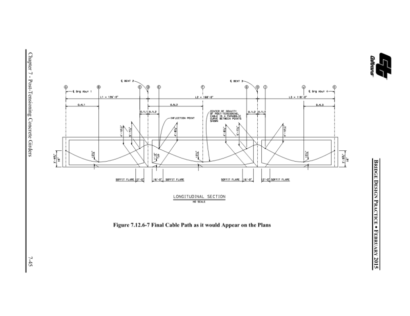
Here is CalTrans detail from their 2015 Bridge Design Practice, on PT girders:


Little hard to read, but basically 0.4L for end span, 0.5L for interior span, 0.1L over supports, compound parabolic profiles. Pretty standard US PT bridge profiles.


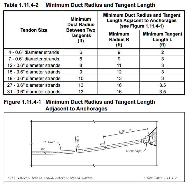
Florida DoT (and I assume other DoT's) require the design engineer to check min. tendon radius, and provide min. tangent length etc:


As far as end-anchorage with sloped ends, the two bridges I have been involved with in the US have both had sloped ends, - as yep, custom recesses had to be fabricated, which is a PITA.


Anyway, as far an answering the OP's question, I think he/she will understand the mechanics of obtaining the tendon slopes etc.

RE: Post Tensioning Cable Slope

Ingenuity,

Not only is it a PITA, it is stupid. if you look at the anchorage location in the diagram showing Fig 7.12.6, they show the anchorage at the CL of the support.

It is not there in practice, it is at the end of the concrete member as shown in your last diagram.

So the profile shape is not correct based on the span lengths to the centre of support. At the end span, it should be to about 4-5" from the end of the member depending on the depth of the recess.

It would be much more logical to have a reverse curve at the end to the support cl and then a horizontal anchorage. And cheaper too!

RE: Post Tensioning Cable Slope

(OP)
Thank you very much for your responses. They have been very helpful.

RE: Post Tensioning Cable Slope

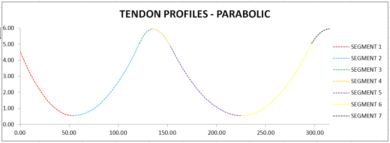
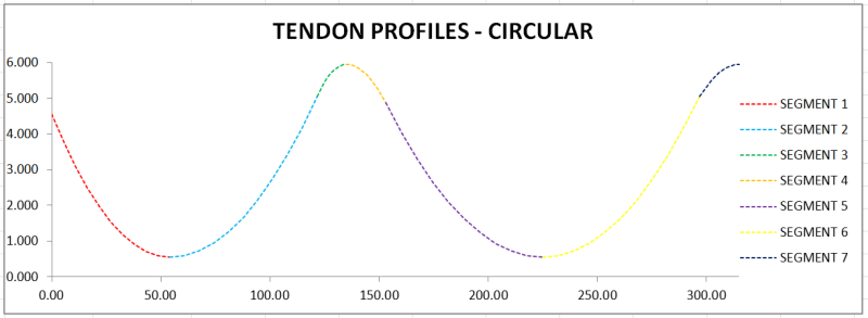
Some what interesting...if you adopt tendon profiles that use CIRCULAR segments, the results for this example problem, in each and every one of the 7 half-tendon profiles, are near identical to using a PARABOLIC segments - to the 3rd decimal place.


For example, the first half-span profile from 0 to 54', here are the profile comparisons:


It is not until you have very small tendon radii/eccentricity ratios that you start to get a few % differences. However, for all practical tendon profiles, even with tight tendon radius, the differences are very, very small.

I am not suggesting using circular profiles, because it is a PITA to use and calc slopes etc, but mathematically CIRCULAR and PARABOLIC profiles will be near identical.

Red Flag This Post

Please let us know here why this post is inappropriate. Reasons such as off-topic, duplicates, flames, illegal, vulgar, or students posting their homework.

Red Flag Submitted

Thank you for helping keep Eng-Tips Forums free from inappropriate posts.
The Eng-Tips staff will check this out and take appropriate action.

Reply To This Thread

Posting in the Eng-Tips forums is a member-only feature.

Click Here to join Eng-Tips and talk with other members! Already a Member? Login


News


Close Box

Join Eng-Tips® Today!

Join your peers on the Internet's largest technical engineering professional community.
It's easy to join and it's free.

Here's Why Members Love Eng-Tips Forums:

Register now while it's still free!

Already a member? Close this window and log in.

Join Us             Close