Continue to Site

Eng-Tips is the largest engineering community on the Internet

Intelligent Work Forums for Engineering Professionals

  • Congratulations cowski on being selected by the Eng-Tips community for having the most helpful posts in the forums last week. Way to Go!

Metal Deck over steel best intermediate basement level

Status
Not open for further replies.

jdgengineer

Structural
Dec 1, 2011
748
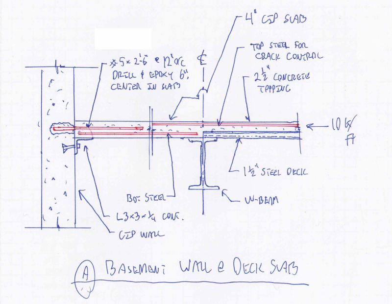
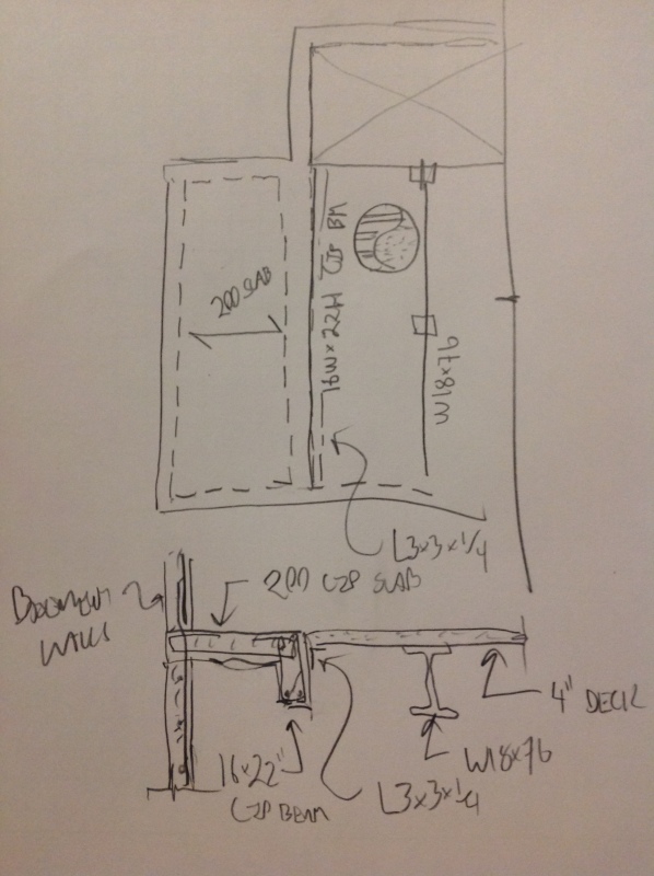
We are working on a multilevel residential basements project. In one area, the basement is roughly two stores deep with 12.5' story heights. We currently have the intermediate level as metal deck with steel beams.

We are running into some problems residing the retaining pressures with the metal deck. Our initial thought was to try and resolve it as a subdiaphragm similar to tiltup construction but we are having issues with the diaphragm shears.

I've discussed using the deck as a compression mber with verco but they weren't entirely helpful and didn't have any testing to back it up. They suggested using only the topping slab (even when parallel to flutes)

How have you been able to make an intermediate basement level work with metal deck? Or is concrete slab really the only feasible option?
 
Replies continue below

Recommended for you

A lot of factors do tend to favour concrete. Can you post a quick plan sketch showing the basics of slopes, framing, and elevation changes? I'd be looking to utilize the topping slab as well rather than relying on the steel deck at all. How does the topping slab fail?

I like to debate structural engineering theory -- a lot. If I challenge you on something, know that I'm doing so because I respect your opinion enough to either change it or adopt it.
 
Based on what you're saying, I think a metal deck system is probably a poor choice. Forgetting vibration and sound problems, it means your deck is spanning maybe 4 or 5 feet, and then you have steel beams (not joists?) at a pretty tight spacing (i.e., lots of beams). Adding concrete means the beam spacing can be 8 feet or more (fewer beams).

But if your hand is forced with metal deck, I would ignore it as a diaphragm and design steel beams as axial struts to take the soil pressure. You'll need them in both directions and to design the wall to span horizontally between beam pockets at the upper basement line. I'd use slip-critical bolts to provide axial connections, as opposed to welding.

 
Thanks guy for initial input. See attached for basement configuration. Don't scrutinize sizes too much as a lot of this needs to be refined heavily.

The lowest level is a relatively small squash court (page 1 of PDF)
Next is a mezzanine level that is a combination of open space for the squash court and matslab (page 2 of the pdf)
Next level is upper basement which is the level in question that currently has metal deck with concrete fill over the mezzanine portion. The rest of the level is matslab (page 3 of the pdf)
Walls below and above right now are overlaid (may be helpful or may be confusing)

We are finding that the resultant earth pressure at the upper basement level is pretty high.
Initially, we were hoping to frame the level with steel beams and concrete pandeck but not sure how to resolve the forces into the concrete pandeck. The rest of the structure has W2 deck with 2.5" topping above. Ideally, we would use that at this level as well.

One thought I had was:

North / South Direction -- Hoping to brace the excavation with the perpendicular steel framing
East Direction -- Hoping to brace the reaction with the adjacent matslab.
West Direction -- This is where I am running into some problems. The reaction is high as the wall is pretty tall due to open squash court level. I believe the reaction from the soil earth pressure was in the magnitude of 10k/ft. We are planning on running perpendicular beams which are not currently shown. The hope was to run them only over the squash court and then we would have developed our "sub diaphragm". With the reactions we have, I' having a bit of trouble getting this to work out.

Another thought I had was to design the concrete topping slab as a compression element which has unbraced length of the beam spacing. I don't love the idea, but at least we are in the strong direction of the deck here.

We can also evaluate spanning the wall horizontally to the return walls (although there is currently a jog in the wall). We could also potentially use tiebacks or other external bracing mechanisms if we absolutely have to.

If all else fails, we can replace the metal deck and steel beams with a elevated concrete slab. This seems to handle the retaining pressures better, but the contractor would prefer pandeck if possible.

Any thoughts? Sorry, I know I probably have not explained well.
 
 http://files.engineering.com/getfile.aspx?folder=6e21f0e2-a93f-477e-b6b0-3b82b7af09e6&file=Basement_Configuration.pdf
jd said:
Another thought I had was to design the concrete topping slab as a compression element which has unbraced length of the beam spacing. I don't love the idea, but at least we are in the strong direction of the deck here.

I do love this. It's only about 0.3 ksi. I've seen this done for main floor slabs on several occasions. I thought that you were dealing with parking or a system that would entail significant vertical stepping across the floor deck. With no stepping you can push the load right through to the other side of the floor and into the opposing soil.

I see no need for it but, as yet another options, I've cast an exterior site girt into foundation walls before. Kinda depends on what you've got going on for shoring/back fill. Contractors dislike it of course.

I like to debate structural engineering theory -- a lot. If I challenge you on something, know that I'm doing so because I respect your opinion enough to either change it or adopt it.
 
Thanks KootK. I am a bit nervous using only the 2.5" topping for compression, loading but seems you would be comfortable with it? I was initially thinking, I'd go with at least 4" if I were to utilize this method. Space is tight, architect would very much prefer the thinner slab. We are planning on reinforcing with #3 bars @ 12" oc each way in the topping slab.

We could also redundantly add in cross beams at 1/3 or 1/4 points running across the length to form a grid. These would essentially be blocking between beams. I think we may have difficulty with the connections in compression for these beams unless we put in a pretty beefy assembly. I think I'd run these in at least 2-3 bays just because it feels right regardless, but could possibly run all the way across.

KootK said:
I see no need for it but, as yet another options, I've cast an exterior site girt into foundation walls before. Kinda depends on what you've got going on for shoring/back fill. Contractors dislike it of course.

We actually have these on the other side but to help serve as shearwalls for a discontinuous moment frame.

 
jd said:
I am a bit nervous using only the 2.5" topping for compression, loading but seems you would be comfortable with it?

Yeah, I would. Obviously not as comfortable as I'd bee with an 8" CIP slab but, then, engineering is a game of good enough, not ideal. I may be more comfortable with this because I stared up at a version of this five times a week for a period of several years. It was the way that the main floor was framed at a below grade fitness facility that I used to frequent. Straight into the deck, no perpendicular beams or stiffeners at all.

At first it did freak me out simply because, at the time, I'd never before encountered the system. Over the course of thousands of burpees and steinborn lifts, I gradually convinced myself that there were solutions to all of the failure modes that I was envisioning. The toughest, for me, was upwards slab buckling. The system that I was looking at had no shear studs. The only uplift connection would have been the deck deformations and the deck welds to the steel framing. I did some ball park number crunching and came to the conclusion that it would be pretty darn tough for the slab to buckle against gravity.

The sketch below shows what I'd fantasize about doing if it were my baby. I like the dowels and bay of solid slab as a means of keeping things sturdy until we're sure that the force is well distributed. Probably overkill. Solid slab soffit could be plywood or 0.6" form deck at the contractor's option.

Capture_jkudtv.png


I like to debate structural engineering theory -- a lot. If I challenge you on something, know that I'm doing so because I respect your opinion enough to either change it or adopt it.
 
Thanks KootK. Makes sense.

Has anyone actually designed this condition before? Anything to be especially cautious of?
 
I have used formulas from the book 'formulas for stress,strain, and structural matrices' to determine the in-plane capacity of a slab, but don't recall specifics too much, and it wasn't a slab on metal deck. here is a shot of the formulation:
slab_comp_nmh8v1.jpg


Roarks may have something similar.
 
I did a crazy house with a wide-open single-level basement, but not a skip-level like you've got. My takeway was I'd rather not mess around with earth pressure.

You are doing what looks like a very high-end residence. I have been taught to treat these more carefully than commercial jobs, although few builders agree. I prefer to shave structural cost tight where the loads are not realistic/sustained loads (live/wind, etc). For actual felt loads such as earth pressure, I like a little redundancy to mitigate risk. I was also taught to tolerate far less vibration or live load deflection.

In your situation, I would build in redundancy by going this route:
-Reinf the wall to span horizontally. If the wall jogs, lap some zees.
--Use concrete topping 2.5" over 2"
--Do "blocking" beams in the first deck span
--Pretension all bolts in your grade-level steel diaphragm. Much debate here but in my opinion this "locks" your steel grid axially.
--Look at it as 18" cantilevered wall. Coming off a 30" footing with return walls, I think you have this load path too.
--Double-check your column sizes etc and see if you can reduce steel or get a column to fit the stud wall above grade. Throw the architect this bone when you insist on concrete topping.
--If you're really pressed on cost, I think your basement wall thickness can be varied for different walls. 18" is beefy.

Good luck. Very interesting dilemma thanks for posting


Thanks for the plate references structSU10, I'll try and dig into something like that.

Appreciate all the input calvinandhobbes10. Seems like we are more or less on the same thought process. I was planning on implementing essentially all of the items you are mentioning.

We are still running through our columns sizes. We gave the architect an 8x8 as a placeholder to be refined later. Basement walls at 18" are also just a placeholder for the most part. Single story walls will likely be 12", I think the multistory walls we will likely keep at 18".
 
- more than I think is necessary.
- less than it sounds like you're planing.
- crazy stiff and robust.
- makes sense with construction sequencing.
- poor quality sketch. Friday = mucho scotch.

IMG_0373_mb4ti1.jpg


I like to debate structural engineering theory -- a lot. If I challenge you on something, know that I'm doing so because I respect your opinion enough to either change it or adopt it.
 
KootK I feel like eng tips needs to have a credit card feature built in. You definitely need some payment for all your thoughts on people's posts.

When our wives respectively leave us for spending too much time on eng tips I hope we can cuddle up under a Canadian fire someplace.

Thanks for the thoughts. I think it's a good idea and worth exploring.
 
Hey, if it sweetens the deal, I've got not one but two adult sized onesies to choose from. Cookie Monster and Voyageur. JD best get his snugly self up here quick though. Work on the Great Wall in the North could start any time.

IMG_0376_qt4bxn.jpg


I like to debate structural engineering theory -- a lot. If I challenge you on something, know that I'm doing so because I respect your opinion enough to either change it or adopt it.
 
kootk said:
Hey, if it sweetens the deal, I've got not one but two adult sized onesies to choose from. Cookie Monster and Voyageur. JD best get his snugly self up here quick though. Work on the Great Wall in the North could start any time.

Just have to pack my Structural Dynamics book by Anil Chopra for some cozy fireside reading!
 
So we've run some calcs on the slab in compression assuming it's unbraced length is the spacing between beams. Parallel to the beams it's about 22' until we hit the perpendicular girder.

We've created a RISA 3D model to analyze the slab for P-Delta considering the gravity loading on the slab combined with axial compression force. RISA 3D is calculating the capacity of the slab following the slender column provisions of ACI 318.

Based on this analysis, we are now looking at a 6" C.I.P slab over the steel beams and omitting the metal deck to save height (architect is pushing very hard on ceiling height). The slab would obviously need to be shored in this instance. We are still planning on designing the beams as composite beams.

I haven't designed a composite beam floor without metal deck. Any out of the ordinary things to be concerned about? Obviously the contractor will not be thrilled with the shoring. Im hesitant to go all poured in place as we have some very large columns landing on steel beams right now and I'm not sure what the concrete beam solution would look like.
 
jd said:
Any out of the ordinary things to be concerned about?

I've never actually done it but, analytically, the design actually seems simpler.

Do you know if erection safety issues will still require that the studs be field installed? Given the limited number of studs that will be involved, it would be nice if you could avoid the mob/demob costs of the stud welding on site.

I also imagine that you'll want some top steel over the beams.

Why is it necessary to eliminate the metal deck? I'd think that introducing a deck into the depth of your 6" slab would hardly impact axial capacity at all.

I like to debate structural engineering theory -- a lot. If I challenge you on something, know that I'm doing so because I respect your opinion enough to either change it or adopt it.
 
kootk said:
Why is it necessary to eliminate the metal deck? I'd think that introducing a deck into the depth of your 6" slab would hardly impact axial capacity at all.

With W2 deck it would be difference of 4" topping slab vs 6" concrete? If we design considering slenderness effects of ACI as mentioned above it makes a difference. Obviously depends on what your definition of unbraced length is. We are considering it to be perpendicular beam spacing which is likely pretty conservative.
 
Fair enough. 6" solid slab it is!

I like to debate structural engineering theory -- a lot. If I challenge you on something, know that I'm doing so because I respect your opinion enough to either change it or adopt it.
 
Status
Not open for further replies.

Part and Inventory Search

Sponsor