×
INTELLIGENT WORK FORUMS
FOR ENGINEERING PROFESSIONALS

Log In

Come Join Us!

Are you an
Engineering professional?
Join Eng-Tips Forums!
  • Talk With Other Members
  • Be Notified Of Responses
    To Your Posts
  • Keyword Search
  • One-Click Access To Your
    Favorite Forums
  • Automated Signatures
    On Your Posts
  • Best Of All, It's Free!

*Eng-Tips's functionality depends on members receiving e-mail. By joining you are opting in to receive e-mail.

Posting Guidelines

Promoting, selling, recruiting, coursework and thesis posting is forbidden.

Students Click Here

Technical drawing reading
3

Technical drawing reading

Technical drawing reading

(OP)
Hi
I am new to this field and recently asigned to develop a cooling system for a cvt transmission.
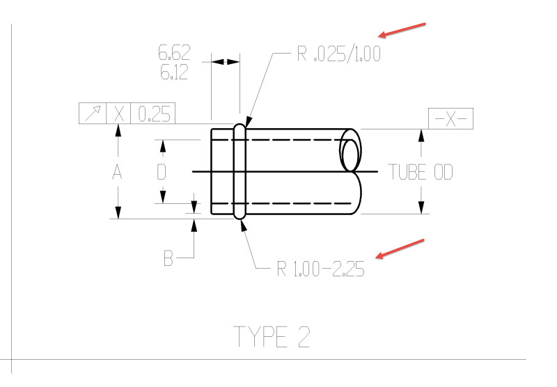
During studying sae j1231 i came across two designations that i can not understand. Any help with this regard is highly appreciated
1- R 0.025/1.00
2- R 1.00-2.25

Best regards
Replies continue below

Recommended for you

RE: Technical drawing reading

A little more context please.

RE: Technical drawing reading

radius callouts?

RE: Technical drawing reading

(OP)
Hi
I know that they are radius callouts but i do not understand the meaning of character "/" between 0.025 and 1.00 or character "-" between 1.00 and 2.25


thx

RE: Technical drawing reading

Is there a table with the values of A, B, and D appear?

RE: Technical drawing reading

The meaning of each character is the same. They both signify a range of acceptable dimensions (from 0.025 mm to 1.00 mm, from 1.00 mm to 2.25 mm). SAE does not adhere to stringent format rules for their standards, so you can see many examples like this when using their standards.

RE: Technical drawing reading

2
As others noted the radius callouts appear to be limit dimensions. I'm sure that if you dig thru all the SAE documents associated with your J1231 standard you'll eventually find a statement like this one from AS4296 - Drawing Interpretation and Standard Machining Practices, Couplings, Fittings and Hose Ends, Fluid Systems: "Unless otherwise specified in this standard, drawing interpretations contained in ASME Y14.5M-1994 shall apply."

Looking at my somewhat more current copy (2009) of ASME Y14.5, section 2.2(a) only includes the use of a dash between the limit values placed in a single line, and not a slash as shown in the OP. "2.2(a) Limit Dimensioning - ........ When expressed in a single line, the low limit precedes the high limit and a dash separates the two values." So it may be possible your J1231 standard document contains a small error.

If you have lots of free time and nothing better to do, there is a formal procedure for submitting corrections to the relevant SAE standard committee.

Hope that helps.
Terry

RE: Technical drawing reading

(OP)
hi
many thanks for all helpful information.

Red Flag This Post

Please let us know here why this post is inappropriate. Reasons such as off-topic, duplicates, flames, illegal, vulgar, or students posting their homework.

Red Flag Submitted

Thank you for helping keep Eng-Tips Forums free from inappropriate posts.
The Eng-Tips staff will check this out and take appropriate action.

Reply To This Thread

Posting in the Eng-Tips forums is a member-only feature.

Click Here to join Eng-Tips and talk with other members! Already a Member? Login


News


Close Box

Join Eng-Tips® Today!

Join your peers on the Internet's largest technical engineering professional community.
It's easy to join and it's free.

Here's Why Members Love Eng-Tips Forums:

Register now while it's still free!

Already a member? Close this window and log in.

Join Us             Close