MSR38-D/DP safety relay circuit
(OP)
I'm trying to understand MSR38-D/DP. The safety relays I am familiar with has redundant chains; a (+) channel and (-) channel. Looking at the diagram, MSR38-D/DP seems to have S11 & S12 as one chain, and S21 & S22 as the other chain. So, as the picture below shows, since the chain circuits are completed, I should get 24V when I put my meter leads across S11 & S21, right? But when I did that, I get no voltage, but the relay has two green LEDs on for the two output channels.
What confuses me more is the seconds diagram; how can S21 be connected to the reset (S34), and S22 connected to the (+) chain?
RE: MSR38-D/DP safety relay circuit
Keith Cress
kcress - http://www.flaminsystems.com
RE: MSR38-D/DP safety relay circuit
" since the chain circuits are completed, I should get 24V when I put my meter leads across S11 & S21, right? "
No, those are both outputs to guards, Estop, ect.
" , but the relay has two green LEDs on for the two output channels "
The green led's indicate K1, K2 are closed.
" What confuses me more is the seconds diagram; how can S21 be connected to the reset (S34), and S22 connected to the (+) chain? "
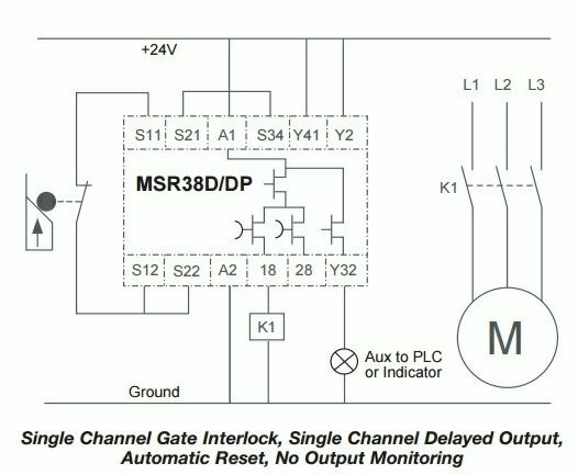
The first diagram is for machine's with Reset buttons, if guard is opened it must be closed and a reset button must be pushed to clear error.
The second diagram is auto reset, the guard simply needs to be closed and error is cleared.
Chuck