FlyingGrimReaper
Aerospace
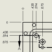
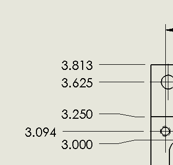
I need some help figuring out a technical issue. The point of this exercise is to organize dimensions in a staircase fashion (cascade) so I can fit the dimensions in the drawing without going beyond the borders of the drawing sheet. I have shortened the line pointing to the number for the vertical dimension into a short L shape extending above the dimension leader. Each labeled dimension is to appear to the top and adjusted slightly left of the previous number to distinguish between dimensions. This should give a cascade look to the labled numbers oriented over each other. (simple enough right?)
Now the problem is that for some reason SolidWorks likes to decide to revert back to the default offset distance for the dimensions overlapping each other (e.g. 1" instead of manually distancing them to 1/10"). I have tried turning off rapid dimensioning, going into document properties and declaring that the offset from model and offset from the next dimension is 1/32" as a test run to verify if it works.
Both have failed and every time I try to move the dimension to stack the numbers it reverts back to the offset distance of 1". Please help me here I am at the end of my wits here and I am very close to paying the boss for the fine of replacing the computer >:-<.