Continue to Site

Eng-Tips is the largest engineering community on the Internet

Intelligent Work Forums for Engineering Professionals

  • Congratulations cowski on being selected by the Eng-Tips community for having the most helpful posts in the forums last week. Way to Go!

Woodworks and Attic Trusses

Status
Not open for further replies.

medeek

Structural
Mar 16, 2013
1,104
A couple simple questions with Woodworks software for all the Woodworks gurus.

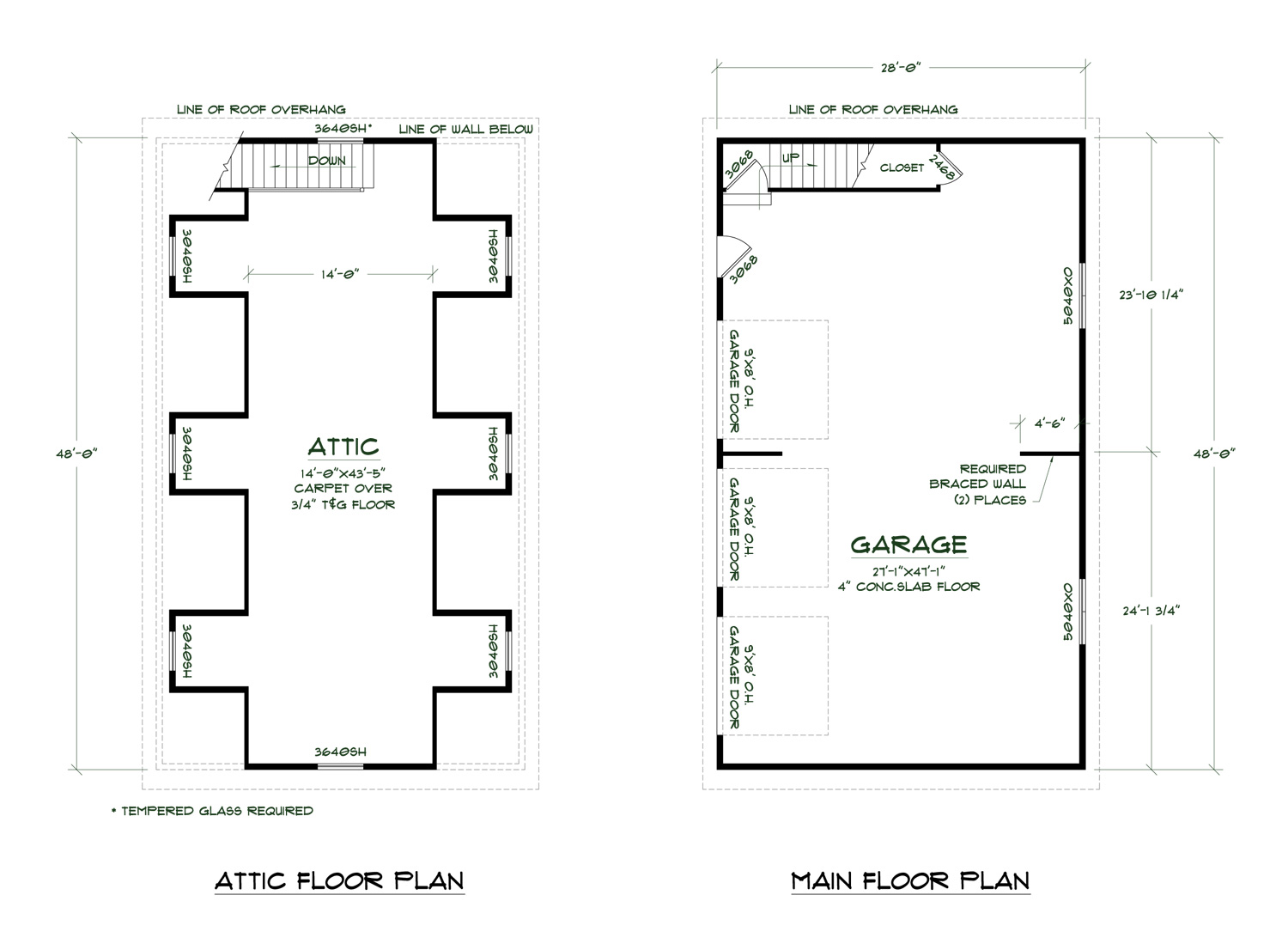
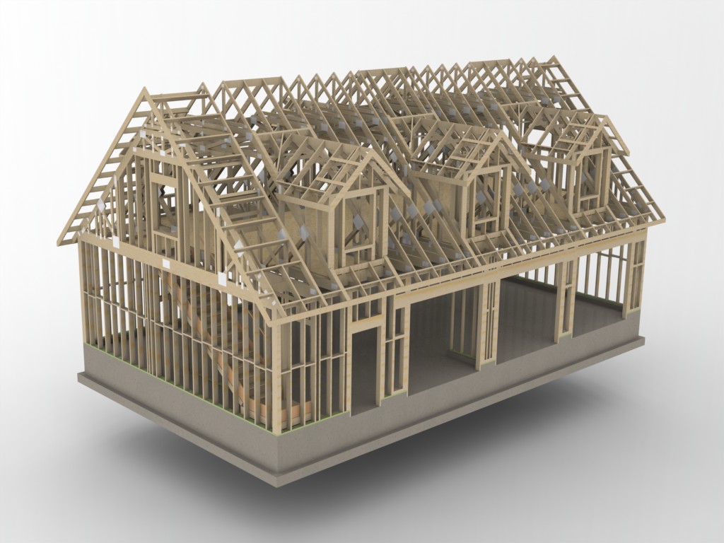
1.) I have a small 12/12 gable roof framed with attic trusses. What is the best way to model this in the software in order to accurately model seimic dead loads from the attic floor space?

2.) Same roof line as above except now I've got a shed dormer (approx. 8ft high) on one side of the gable roof with a 3/12 pitch.

A confused student is a good student.
 
Replies continue below

Recommended for you

As a related but somewhat different question, does anyone do residential wood design with Risa3D? and if you do, do you also need RisaFloor as part of the package to do load takedowns and shearwalls? I would like to further explore the capabilities of Risa3D in some detail.

A confused student is a good student.
 
I'm not sure if the software has the capability to model dormers (ie. 12/12 attic trusses with dormers) properly. With a shed dormer I'm wondering also how to best deal with shear wall action for this upper level. Does anyone have experience or any past examples working with dormers?


A confused student is a good student.
 
I'm finally getting around to working up the engineering for one of my own garage designs that I did a couple years ago:

GARAGE4828-A6D-3_ISO1_800.jpg


The addition of the dormers may not be signficant but I would like to take a serious look at this and see how much difference we are talking. Also related to this are the roof diaphragm loads. By creating large discontinuities in the roof diaphragm how does one rationally analyze the diaphragm.

With attic trusses the gable ends, when properly sheathed will act like drag trusses and I think one can safely assume that the gable shear walls can be regarded as normal.

A confused student is a good student.
 
I'm a trying to analyze this particular design in the Woodworks Shearwall software.

A confused student is a good student.
 
This garage design is a perfect example of what happens when you try to design a structure using the IRC and don't have a clue about real lateral design:

GARAGE4828-A6D-3_FLOORPLANS_SIMPLE_1500.jpg


Look at the interior shear wall line between the garage doors. A few problems:

1.) The rigidity of these smaller shear panels (9') will be significantly less than the two exterior walls (28') so they will attract less load. They won't be doing much in reality, are they worth all the trouble.

2.) The middle dormers fall right on top of them (ladder framing to girder trusses). There will not be a continuous load path to the roof diaphragm. Maybe solid blocking inline with the shearwall and between all of the ladder framing will help with this.

3.) A grade beam will need to tie the two halves together otherwise the overturning will exceed the foundation's capabilities at the int. shearwall line.

4.) The int. shear walls split up the garage space which doesn't sit well with the owner/occupant.


A confused student is a good student.
 
Wrt your point 1, the real value in such short walls is to afford stability to the diaphragm and give you something to break the long load path for your lateral loads to travel in your short direction. Unless you considered your timber floor to be a rigid diaphragm, these are still valuable and do take force.
 
Yeah, I'd probably omit the short walls myself. Without them, your aspect ratio is still less than 2:1.

I like to debate structural engineering theory -- a lot. If I challenge you on something, know that I'm doing so because I respect your opinion enough to either change it or adopt it.
 
And your attic floor deck will add diaphragm capacity and rigidity.

I like to debate structural engineering theory -- a lot. If I challenge you on something, know that I'm doing so because I respect your opinion enough to either change it or adopt it.
 
When you are doing IRC lateral design, take off your engineer hat. Sometimes it doesn't make sense, it just is. It is also usually the cheaper design. I am not a fan of it myself, but I understand that it works. But if I wanted to, I bet I design an IRC compliant house that would fall apart under a real world scenario.

Personally, I try to do IBC (engineered) design for all of the houses I design. It makes more sense to me and I find it easier.

When I am working on a problem, I never think about beauty but when I have finished, if the solution is not beautiful, I know it is wrong.

-R. Buckminster Fuller
 
My first observations may have been a bit simplistic.

Unlike most roof diaphragms that I consider this one is slightly different with the addition of the attic floor sheathing. In a sense you have a triangular tube formed by the attic floor and roof sheathing combined with the attic trusses. The question really is how to determine the stiffness of this "modified diaphragm" and also the diaphragm shear loads. I would not expect this to be equivalent to a 4/12 pitch roof diaphragm with only roof sheathing.

If you disregard the IRC for a moment and look at the reasoning or need for the interior shearwall it becomes clear to me that the deflection of the diaphragm is the primary reason to include a shearwall at this central location. If the diaphram and hence wall deflection is too excessive at the mid point of the building then it definitely makes sense to provide a structural element to counteract this deflection. The loads to the two ext. shearwalls is really not a factor here since they are both long enough to provide plenty of shear stength while having manageable unit shear and holdown forces.

The interior shearwall transmits it loads to the attic floor diaphragm which is probably not as good as getting them directly to the roof diaphragm above but I think it will work in this case. To make this work I would call out solid blocking inline with the shearwall below with nailing at 4" o/c spacing. This blocking will fit between the attic floor ladder framing the full width of the building and also require a continuous strap on the underside to pickup the collector forces (tension).

The gable wall next to the stairwell should probably be balloon framed up to the roof rather than using a gable end attic truss as shown below:

GARAGE4828-A6D-3_FRAMING4_1024.jpg


The problem I see here is that there is a hinge point created with no lateral support from the floor diaphgram, but it is only about 60% of the building width so I may be splitting hairs but I thought I might point that out.


A confused student is a good student.
 
To simplify the wind loading in the longitudinal direction one could treat the three dormers per side as one dormer since the dormers are in the shade of each other. The net affect is as if there is only one dormer with it respective windward and leeward roof and wall forces.

I contacted Woodworks support and the provided me with their work around for dormers but it doesn't really work in my opinion. At this point I just have to sit down and run the numbers manually or program my own solution to the problem which is in the works but will take some time.

In fact, after giving it some serious consideration I would actually like to program an application similar to the Woodworks Shearwalls program but with a more flexible, updated and intuitive interface and the ability to handle dormers and attic trusses like this current problem, a bit ambitious, I know.

A confused student is a good student.
 
For the wind loads on the dormers in the transverse direction it is merely a matter of determining the windward and leeward wall forces on the dormers and replacing the roof windward and leeward forces using the total cross sectional area of the dormer profiles. I would actually be interesting to see which gives an overall larger shear load to the shearwalls below, dormers included or dormers ignored.

A confused student is a good student.
 
The other complication with this design is the large holes that the dormers introduce into the roof diaphragm/sheathing. In some ways this is similar to punching some rather large holes in the web of a TJI (I Joist) approximately mid span. What does it do to the diaphragm rigidity and shear? The holes for the dormers are large enough that it is hard to consider this diaphragm as continuous.

A confused student is a good student.
 
Looks like Malone's book has a good treatment of openings in diaphragms. With the dormers as large as they are I don't think this design will calc out. Maybe the contribution by the floor diaphragm will save the design.

Yet another problem with this design is the opening in the floor diaphragm at the stairwell on the north wall. The transfer diaphragm at the top of the stairs is going to be very heavily loaded.

Who knew residential structural engineering could be so complicated, I'm about ready to throw in the towel on this one.

A confused student is a good student.
 
1) I'm not sure that I buy the dormer shading argument.

2) For short direction lateral, maybe it's best to use just the attic floor diaphragm. It should be pretty strong and stiff.

3) Wood lateral is the worst lateral in my opinion. We feel your pain. This, and the profit motive, are why we mostly fall into prescriptive design methods.

4) Every day I have to remind myself that my job isn't about "knowing" anything. Structural engineering is about the moderately intelligent proportioning of things, nothing loftier.

5) Take comfort in the fact that no one is doing this stuff any better than you. In fact, I guarantee that most people are being far less conscientious.

I like to debate structural engineering theory -- a lot. If I challenge you on something, know that I'm doing so because I respect your opinion enough to either change it or adopt it.
 
Status
Not open for further replies.

Part and Inventory Search

Sponsor