SiggiN
Marine/Ocean
- Mar 18, 2019
- 33
Hi all!
Suppose you have this two storey wall diaphragm:
I am curious about how to distribute the vertical loads (load from roof, snow, wind, floor etc.)and verify that deflections above the windows are small enough.
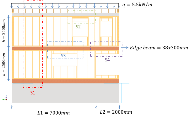
All studs are spaced 600mm apart (except around windows)
I've marked some areas of interest; S1, S2, S3 and S4
My thoughts/questions:
S1 : Should be straight forward, load is transferred all the way down to the concrete wall.
S2: Can the window header be modeled as a simply supported beam? Where the reaction forces are transfered through the studs to the "edge beam" below as point loads. The studs carrying the extra load will be engeineered individually to verify axial integrity.
S3: To check the deflection of the "edge beam" passing over the window. Should the "edge beam" be modeled as a continious beam with pinned connections at every full stud? With distributed laod from roof, floor, wall and any point load from S2 (reaction forces)?
S4: The "edge beam" will be cantilever at this end. I doubt the dimension shown is sufficient, so might reinforce with steel. Any thoughts in general on postless corner window framing? 2m cantilever might be too much?
- Using some made up numbers, would the free body diagram below be realistic for the "edge beam"? I'm especially curious about your thoughts on the spacing of the pinned connections
All comments/thoguhts are highly appreciated!

Regards
Siggi
Suppose you have this two storey wall diaphragm:
I am curious about how to distribute the vertical loads (load from roof, snow, wind, floor etc.)and verify that deflections above the windows are small enough.
All studs are spaced 600mm apart (except around windows)
I've marked some areas of interest; S1, S2, S3 and S4
My thoughts/questions:
S1 : Should be straight forward, load is transferred all the way down to the concrete wall.
S2: Can the window header be modeled as a simply supported beam? Where the reaction forces are transfered through the studs to the "edge beam" below as point loads. The studs carrying the extra load will be engeineered individually to verify axial integrity.
S3: To check the deflection of the "edge beam" passing over the window. Should the "edge beam" be modeled as a continious beam with pinned connections at every full stud? With distributed laod from roof, floor, wall and any point load from S2 (reaction forces)?
S4: The "edge beam" will be cantilever at this end. I doubt the dimension shown is sufficient, so might reinforce with steel. Any thoughts in general on postless corner window framing? 2m cantilever might be too much?
- Using some made up numbers, would the free body diagram below be realistic for the "edge beam"? I'm especially curious about your thoughts on the spacing of the pinned connections
All comments/thoguhts are highly appreciated!
Regards
Siggi