thejonster
Structural
- Feb 8, 2011
- 69
I need bracing for my steel beam in uplift and this is bugging me.
I've noticed in PEMB that huge tapered built up plate girders with tiny angles braces to purlins don't seem change the size purlin it's attached to, and the tiny angle doesn't seem like it could carry a big kicker load. In this risa model you can see the connection forces are higher than simply supported loads. It would seem that the load from the purlins could be much higher than the bracing force it's mainly intended for, and that prying force increases the closer the brace is to the end of the beam by the deflecting purlin, possibly amplifying the force the smaller the brace is.
Are the braces usually designed for the bracing force only, how do you guys justify or account for this prying? Is buckling in the brace angle used to justify ignoring this prying?
From what I hear about how PEMB are designed, my guess is that it is ignored since you give the purlin a simply supported load path and call it good. If that's the standard of care I'd like to know your reasoning


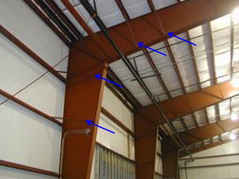
I looked for a better picture, but you guys have all seen this tiny 1x1 bracing for huge built up sections
I've noticed in PEMB that huge tapered built up plate girders with tiny angles braces to purlins don't seem change the size purlin it's attached to, and the tiny angle doesn't seem like it could carry a big kicker load. In this risa model you can see the connection forces are higher than simply supported loads. It would seem that the load from the purlins could be much higher than the bracing force it's mainly intended for, and that prying force increases the closer the brace is to the end of the beam by the deflecting purlin, possibly amplifying the force the smaller the brace is.
Are the braces usually designed for the bracing force only, how do you guys justify or account for this prying? Is buckling in the brace angle used to justify ignoring this prying?
From what I hear about how PEMB are designed, my guess is that it is ignored since you give the purlin a simply supported load path and call it good. If that's the standard of care I'd like to know your reasoning
I looked for a better picture, but you guys have all seen this tiny 1x1 bracing for huge built up sections