Tek-Tips is the largest IT community on the Internet today!

Members share and learn making Tek-Tips Forums the best source of peer-reviewed technical information on the Internet!

  • Congratulations cowski on being selected by the Eng-Tips community for having the most helpful posts in the forums last week. Way to Go!

Why this line showing up on both faces?

  • Thread starter Thread starter kingston123
  • Start date Start date
K

kingston123

Guest
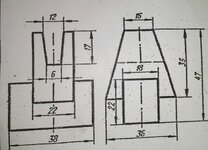
Desired diagram: View attachment 2145

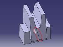
My diagram:View attachment 2146 (see the marking)

I applied edge chamfer on top edge (Length 1\length 2) as (10\35)
 

Attachments

  • 2.jpg
    2.jpg
    143.1 KB · Views: 4
  • 1.JPG
    1.JPG
    45 KB · Views: 3
I'm not sure why those lines show up. Maybe a software bug in CATIA?

Using Chamfer to taper the front and rear faces is an interesting technique. Chamfers are normally used to eliminate a sharp corner, like a fillet. They normally are short and don't extend the entire length of a face, like you've done. But there's nothing wrong with using a Chamfer for the tapered faces. Maybe it was confused with the slot in the middle?

You didn't show the tree diagram, so I have no idea what features were used to model what you have so far. And there are many ways to model a part like this.

But I suggest replacing the Chamfer with a Sketch and use a Pocket to cut-off the faces, like the picture below.

View attachment 2149
 

Attachments

  • KINSTON4.JPG
    KINSTON4.JPG
    38 KB · Views: 3
Last edited:
Maybe it was confused with the slot in the middle?

YES. I applied edge chamfer before applying slot(pocket). Then I didn't get that line.
 

Part and Inventory Search

Sponsor

Back
Top