Continue to Site

Eng-Tips is the largest engineering community on the Internet

Intelligent Work Forums for Engineering Professionals

  • Congratulations cowski on being selected by the Eng-Tips community for having the most helpful posts in the forums last week. Way to Go!

Welding Capacity Calculation 7

Status
Not open for further replies.

JohnRwals

Structural
Jul 8, 2020
151
Hello!

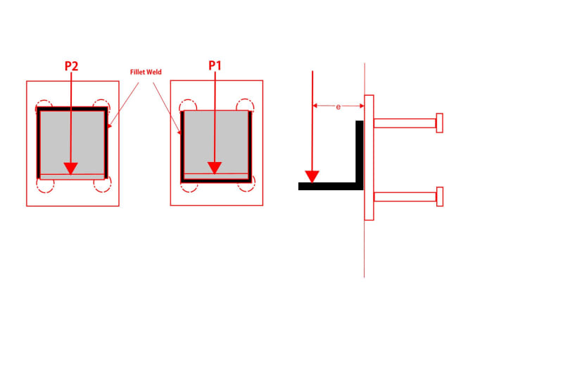
P1 and P2 have exactly the same conditions except top, bottom horizontal welding.
I thought P2 could support greater vertical load.
But...
Which one do you think can support greater load? Why?

Thanks!

JW
R
Welding_Capacity_otqiin.jpg
 
Replies continue below

Recommended for you

in your sketch orientation P2 would be a more efficient connection as it has the weld on the edge of the angle which is in tension for the P*e resisting moment couple. P1 the two vertical welds are being asked to handle P and the tension component of the resisting couple.

My Personal Open Source Structural Applications:

Open Source Structural GitHub Group:
 
To specifically address your question on capacity though:
If the welds are all the same effective throat and you ignore any bearing compression development with the embedded plate.

The two configurations have equal capacity using an elastic analysis because the elastic section modulus Sx is unchanged.

My Personal Open Source Structural Applications:

Open Source Structural GitHub Group:
 
The horizontal weld on P1 is more difficult to make.

Rather than think climate change and the corona virus as science, think of it as the wrath of God. Feel any better?
-Dik
 
Hey Celt83 - I don't think those two conditions will have the same Sx.

weld_as_line_qe5q7a.jpg
 
azcats - I believe that the Sx(bottom) of one configuration becomes the Sxtop of the other and vice-versa. I believe that is what Celt83 was alluding to in his identification that the Sx would be the same.
 
Azcats:
The only difference will be which is Sw,top or bottom with the same applied moment = P*e, consistent effective weld throat, and no compression development with the embed.

for Bending stress:
In the P2 orientation the max unit stress on the weld will be a compressive stress at the bottom of the vertical weld lines, P*e/Sw,bottom
In the P1 orientation the max unit stress on the weld will be a tensile stress on the top of the vertical weld lines, P*e/Sw,top

However with the flipped orientation Sw,bottom for P2 is = Sw,top for P1, so the magnitude of the stresses will be equal

For Vertical Shear Stress:
In all cases the contribution to the unit stress from P is just P/A,weld, where A,weld is assumed to equal to total length of weld.

With the magnitude of the weld unit stress being √ σ,shear^2 + σ,bending^2 , resulting in equal design unit stresses for either orientation.

My Personal Open Source Structural Applications:

Open Source Structural GitHub Group:
 
My mistake - I understand what you're saying now. My head was only looking at tensile stresses...
 
The fact is Ix is identical for both cases. Upon finding neutral axis, ATOP = ABOT, then for same bending on the cross section T ≡ C, and lever arm distance remains the same, so the capacity.
 

I agree with you... P2 can support greater vertical load. If we consider shear , both alternatives have exactly the same shear capacity. However for bending, P1 upper sections of vertical weldments will experience more tension stress and will start yielding before P2 case. This is due to bearing compression development with the embedded plate which the NA will be lower than P2 case.
 
Are we all agreed that P2 will be greater than P1? I was a little confused by some of the answers, but the P2 arrangement is stronger because, while they are equal in shear capacity, for bending, P2 has the equivalent of 4 welds, top, bottom and 2 sides. No reason to ignore compression against the embed plate.

BA
 

and to reiterate... it's easier to weld... seems like a win win situation.

Rather than think climate change and the corona virus as science, think of it as the wrath of God. Feel any better?
-Dik
 
Numerical example. Note the small discrepancy in tension and compression forces is due to roundoff.

image_x49cyb.png
 
r13, your calculation assumes the face of the angle against the embedded plate is extremely rigid compared to the embedded plate and you're neglecting any bearing pressure between the angle and the embedded plate.

For P1, the horizontal weld does nothing if the angle is placed firmly against the embedded plate - in this case there is direct bearing between angle and plate. If there is a gap then the weld must transmit the compressive forces, but it is more likely that the angle would be placed tight against the embedded plate.

For P2, I don't think the horizontal weld is fully effective until the vertical welds start to fail. Think about how the angle has to deform to deliver load to the horizontal weld...you would develop separation between the angle and embedded plate, which can't happen because of the vertical weld.

For both cases the horizontal weld is mostly for show. I consider both details to be equal. P2 would be better if you could flip the angle and put the vertical leg down and keep the weld on top.
 
R13, analyzing stresses in a weld group as equivalent couple forces is not a correct approach. In an extreme case, this method could overlook a peak stress at the tension toe of a fillet weld resulting in progressive/"unzipping" failure.

While we all appreciate your enthusiasm and contributions to this forum, you do tend to post incorrect or misleading statements with alarming frequency.

----
just call me Lo.
 
CANPRO,

The calculation was to clear up my comment made before - strength-wise, the two cases are identical.

I don't quite understand your bringing "bearing" into traditional weld design calculation. Question for you, don't you count the horizontal weld for shear, though it's not needed for compression?
 
I agree P2 with the angle flipped (or stiffened) is the highest capacity configuration.

I think that even as shown, the P2 horizontal leg will contribute slightly to the weld group capacity because of some weld ductility at the top corners. But depending on the proportions, I would be unlikely to rely on it fully or even partially due to the concerns CANPRO raised.

----
just call me Lo.
 
r13, draw a free body diagram of the angle - there are contact forces (bearing) between the angle and the embedded plate that most definitely effect the weld demand.

I would count the horizontal weld for direct shear resistance, but in comparing the two details this contribution is identical.
 
Status
Not open for further replies.

Part and Inventory Search

Sponsor