Continue to Site

Eng-Tips is the largest engineering community on the Internet

Intelligent Work Forums for Engineering Professionals

  • Congratulations waross on being selected by the Eng-Tips community for having the most helpful posts in the forums last week. Way to Go!

W-beam reinforcement

Status
Not open for further replies.
Jan 10, 2023
12
I created this account to start a thread at the structural engineering general discussion forum but, as a student, I'm not able to. If any benevolent reader with that ability would like to copy and paste/post this question there, that would be greatly appreciated. If that doesn't happen, I hope some students find enough interest to take the time to reply with their thoughts. I understand these forums are for engineers helping engineers, which isn't the case, but I thought I'd give it a go.

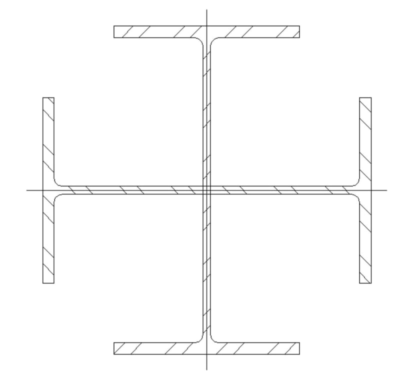
Picture a four-way beam supported by a single central column.

Now imagine a W-beam (W 10x19) 10 feet long with the top flange cut perpendicularly 1 foot away from the ends and the web cut diagonally from that point to the point at the bottom of the web 4 feet away from the ends where the bottom flange is cut. Flip the split sections around so that the top is bottom and remove all 3 bottom flanges. Now join the T-shaped ends of the split sections to the center of the remaining beam having removed the bits of flange that overlap. There should be a square opening above the welded webs equal to the width of the flange.

This is welded to a plain cruciform column with foot long "legs" in each one of the four directions. The beam ends up shaping the typical moment diagram of a cantilever.

Regarding the load, it is quite eccentric. For practical purposes, consider a point load of 3000 lb at the end of each yard long unsupported span.

The short column is to be reinforced with gusset plates where it is reduced from foot long "legs" to a span (9 inches) halfway between the beam and the base plate.

The question is: does the top and only flange of the beam need reinforcement? If so, are there discreet solutions? This is obviously a small project. I'm not sure welding round bars to the fillet between flange and web will do the trick, for example.
 
Replies continue below

Recommended for you

Hi

You will probably get better responses if you provide a sketch.

“Do not worry about your problems with mathematics, I assure you mine are far greater.” Albert Einstein
 
Agreed, happy to help but having trouble following the description.
 
Are you looking at something like:

Clipboard01_rooqry.jpg


I had a project once where this was a column member and the sections were W21x55...

-----*****-----
So strange to see the singularity approaching while the entire planet is rapidly turning into a hellscape. -John Coates

-Dik
 
Without running the numbers, I think it is unlikely that the top flanges require reinforcement.

My first suspicion of the weak link (if an part is inadequate for the given loading, it may be entirely OK), would be the bottom "stem" which is in compression and would tend to buckle.
 
Lomarandil, would adding gusset plates the same size as the ones below that stem provide an overall solution?
 
Glue that up from heavy paper card stock or styrene sheet and then give it a push where you expect the load to be. (1/12th scale)

I'd expect a close race between twisting failure and buckling.
 
Concur with 3DD... Is the cruciform section in the middle? You might be better served using an HSS 10x10 or 12x12... Cruciform W sections have very poor torsional resistance. and I can see the web of the cut beams in compression and prone to buckling, giving rise to a twisting motion as 3DD notes.

-----*****-----
So strange to see the singularity approaching while the entire planet is rapidly turning into a hellscape. -John Coates

-Dik
 
dik, the cruciform section is the plain X-shaped section the top of which is where the bottom flange of the W-beam would be. What you see in the middle is simply the web of the beam exposed.

Would this modification help?
 
 https://files.engineering.com/getfile.aspx?folder=fd38e8d3-1b58-4f22-995c-f05631f4ca26&file=sketch.jpg
I have a hard time seeing how those top flanges provide any benefit to the system. If a load is applied to the tip of one cantilever, the top of the section will want to carry tension forces.
Because the ends of the flange aren't attached to anything, the flange won't have any tension capacity, and this becomes a plate bending problem instead of a beam bending problem or WT bending problem.
 
I still think you should be looking at an HSS section for the column, rather than a cruciform shape.

-----*****-----
So strange to see the singularity approaching while the entire planet is rapidly turning into a hellscape. -John Coates

-Dik
 
Back to the original question:
WouldbeBeenArchitect said:
The question is: does the top and only flange of the beam need reinforcement?

What do the numbers say? The top and only flange of the beam only needs reinforcement if it's not strong enough.
Depending on the load, material, plate sizes, etc, the reinforcement may or may not be necessary.

It's an odd shape for sure. I can't think of any instance where this shape would be a very good option.
Dik has pointed out possible deficiences in the column section, I think that the beam section is totally ineffecient, but the system certainly has *some* capacity to carry a load.
 
If the loads at the ends of the arms are downwards, the webs of the arm are likely to buckle, and the missing flange load path in the middle (the open square) is likely to have a tensile issue locally.
If the loads are upwards, then the flange load path is also bad, with the flanges likely to cripple.
In both loading directions the arms look susceptible to lateral-torsional buckling.
So, you likely need stiffeners/flanges at the bottoms of the arms, and fill in the square hole in the top flanges with a plate welded to everything.
The column part looks like a load path mess also ...........
 

We have some local shelters that are constucted with a similar cantilever and they are fabricated out of plate material, with a top flange and tapered web. They are not overly efficient, but are quite attractive.

-----*****-----
So strange to see the singularity approaching while the entire planet is rapidly turning into a hellscape. -John Coates

-Dik
 
Once20036, Lomarandil thinks reinforcement may not be necessary. As you pointed out, the ends of the flange aren't attached to anything, so the problem is attachment.

SWComposites suggested welding a plate. I know this sounds strange, but I wanted to use the square opening for glasswork. By the way, the loads at the tips are downwards. What would stiffeners other than flanges look like at the bottom of the web?

dik, I'll look into the hollow section for the column. The reason for the cruciform section, besides integration with the beam, is a chamfered cube at the capital (bigger section) with concrete forming the cube and the steel plates making the chamfers at the edges.
 
If the web of the beam isn't a problem, I could add more gusset plates (though not triangular) to solve the flange, like the sketch attached.

If it is, and it seems to be, I could add steel flats to support the ends of the flange. In section, this would resemble dik's image above. The flats would be transverse stiffeners of the web of the beam and longitudinal stiffeners would brace it. I'll try to upload this sketch too.
 
 https://files.engineering.com/getfile.aspx?folder=7b55464a-facf-49c1-ada3-6c00f973fc03&file=sketch.jpg
Once20036, I'm not an engineer. I used websites with calculators or tables and such. Initially, I had a W 8x13, but this seemed like it would fail. With a W 10x19, the extra 2 1/4 inch in depth of the 1/4 inch thick web plate alone (rectangular in shape) seemed more than enough for the load with a safety factor over 2. Having something similar to dik's account of a local shelter in mind, I thought, cut the web in half so it tapers and, with the flange, it should be enough. The flange provides the base for a concrete slab which has a hole in it's center. I'm seeking a professional opinion here.
 
Looking at the model, it's difficult to design, even for good engineers. The issue is not likely strength, but stability... a whole different 'critter'.

-----*****-----
So strange to see the singularity approaching while the entire planet is rapidly turning into a hellscape. -John Coates

-Dik
 
Status
Not open for further replies.

Part and Inventory Search

Sponsor