This tolerance is the cord height used to trim the edges in the drafting views.
Tolerance 0.0 is an "unreasonable and unachievable" target *, - you can get pretty close but long computing times and to no use.
Instead try this. Fit the entire drawing. Edit "that view" set the view tolerance to 0. Apply.
NX will then compute a value which NX considers reasonable and update the view. Now zoom that view and look for any errors.
If none, save the drawing, you are done.
If you can see any "errors" , PRINT to paper the same drawing and again look at these errors , - Still visible on the paper or did you become fooled by zooming ?
If you can see an error, which happens, zoom the view to a reasonable scale, then again set the tolerance to 0. NX will find a new tolerance value where the error probably disappears.
( if there still is an error, check if the model is corrupted or contains interference's.)
* Computers calculates with a given number of decimals, there is always some form of rounding.
-the objective for all cad systems is to keep that rounded "error" smaller than visible/noticeable by the user.
Another factor is that all shapes are drawn on screen using straight lines , you sometimes have to do "Update display" to get a nice view.
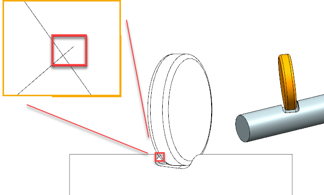
The example below is two cylinders at an angle in between . The cylinders do not touch.
the tolerance is what NX defaulted to.
The wire frame view looks good, no visible errors.
But, when i zoom ridiculously , a tiny error will become visible, but, the paper print of this will be perfect. NO errors visible.
this error is when measured using the "screen distance" ~11 μm.
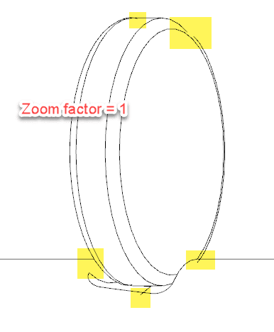
The same view, screen captured with zoom factor = 1. ( which should be pretty similar to printed)
the view tolerance is manually set to 2.
Regards,
Tomas