SK,
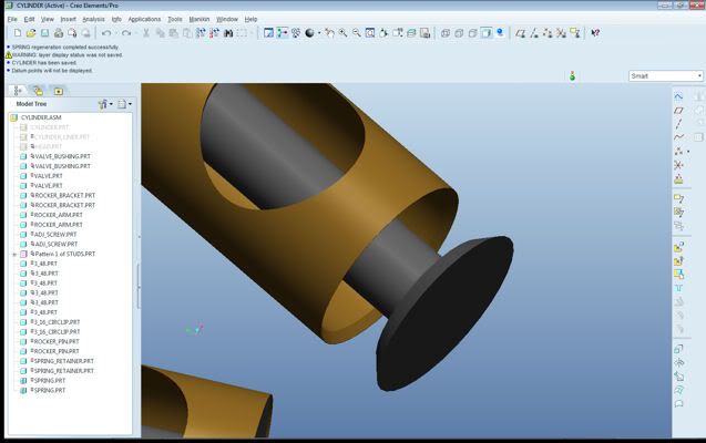
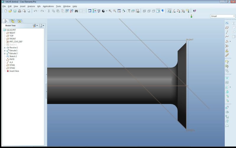
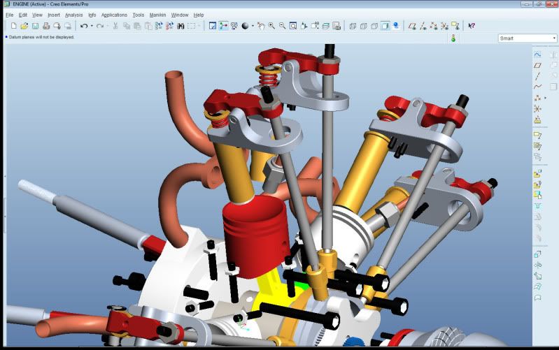
I would recommend focusing on a different area to capture valve seat limits. I've modeled hundreds of valve trains and always use the slider or cylindrical joint axis of the valve to control the seating "event". I find out exactly what the limit is of the valve's travel and assign a joint axis limit to the valve's slider/cylindrical joint. If you do enough testing or research previous work, you might even find non-linear relations to model the valve bounce correctly using external forces. Using a cam surface as you've done so far will introduce an off-centered load into the system. If your goal is to have an accurate dynamic model of the system, you'll want to limit the valve's joint movement. Be sure to create the joint axis directions properly to get "positive" valve motion during opening and establish your joint axis zero properly where the valve will contact the seat. You can use the coefficient of restitution here to help capture valve bounce. Your lift off (for valve float) will come by the way of your cam pair definition between the valve tip and the rocker pallet (or underside of a direct acting lifter) and/or the cam-follower cam pair - make this "Enable Liftoff" and you'll be able to model valve float. Set-up properly, the valve spring will take care of your closed load as well. It's possible to capture virtually all the dynamics of a hydrauliclly lashed valve train - I've had up to 24 DOF in one system to cover all locations of compliance within a hydraulic valve line with extremely high correlation to test data.
BTW - when you simply drag components with liftoff-enabled cams, you can easily get the bodies to jump/pass through each other. Running a dynamic analysis will take care of this. Also, for future questions along these lines, it might be best to post in the analysis section - this type of topic is what is normally discussed here - I just happened to stumble upon it - hope this helps,
Kaz
Edited by: Kaz Z06
