Continue to Site

Eng-Tips is the largest engineering community on the Internet

Intelligent Work Forums for Engineering Professionals

  • Congratulations waross on being selected by the Eng-Tips community for having the most helpful posts in the forums last week. Way to Go!

Typical boundary conditions for pressurized stiffened panel 1

Status
Not open for further replies.

juju_CAE

Mechanical
May 7, 2021
3
Hey,

I am trying to run a local FEA of a portion of stiffened panel withstanding only lateral pressure.

I would like to know what are the standard boundary conditions to apply in such a case.

BC_pressurized_stiffened_panel_nrlsng.png


Thanks in advance for your help.

Regards
 
Replies continue below

Recommended for you

Hi

How is the edges of the stiffened panel attached to its adjacent component?

“Do not worry about your problems with mathematics, I assure you mine are far greater.” Albert Einstein
 
Hi,

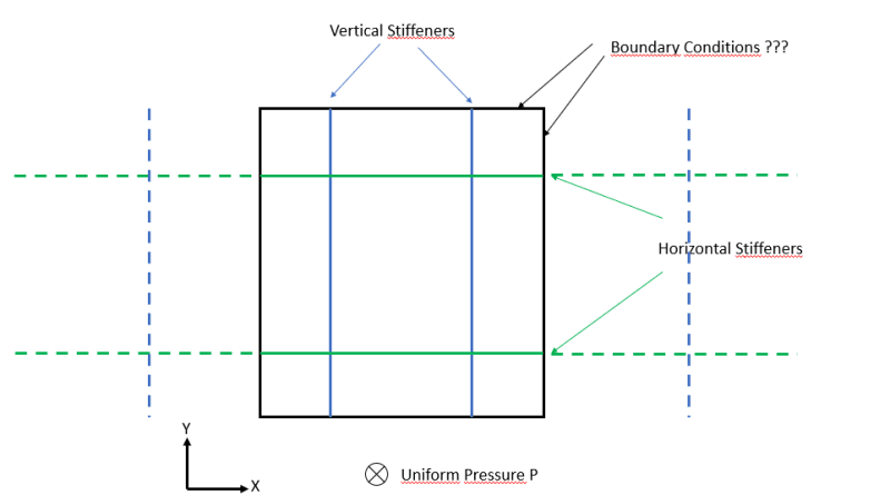
If I had to solve this problem I would try following approach. I would put the the boundaries exactly in the middle between vertical and horizontal stiffeners.

I assume you have a liquid on the inside, causing the lateral pressure to change in the vertical direction.

With the vertical boundaries you will symmetry on both sides of the boundary. With the horizontal boundaries that line will not have symmetry on both sides, but could be assumed in a first approach I think, when the distance between the horizontal stiffeners is not too large.

In order to get a better boundary condition formulas from Roark could be used, or a rough estimate with the differential equations for a bending plate. The latter could take considerable time, unless a publication with this can be found, which is likely, as this is a common problem.

Good luck.
 
I'd model the panel and the stiffeners, and constrain the edge as SS.
And I'd use a finite stiffness constraint, 10^5 or 10^6.

another day in paradise, or is paradise one day closer ?
 
I think the boundary conditions need to represent the actual panel edges and the stiffener details.

Among the options that may, or may not actually exist on your real-life part
The model is a small piece of an Infinite panel so the edges are actually free to rotate and translate as allowed by the rest of the panel stiffness.
The stiffeners ending at the edges of the panels as shown.
The stiffeners are continuous and continue on for several feet
Edges constrained from any rotation ( probably not very realistic, even if the model is one complete end panel on a welded box. )

Probably several more possibilities, but only one or two will come close to simulating what the actual part is like.
 
Ok

Thank you for your answers and explanation

 
Status
Not open for further replies.

Part and Inventory Search

Sponsor