Continue to Site

Eng-Tips is the largest engineering community on the Internet

Intelligent Work Forums for Engineering Professionals

  • Congratulations waross on being selected by the Eng-Tips community for having the most helpful posts in the forums last week. Way to Go!

Two beams fitted inside each other, spot welded at the ends. What load size can they withstand? 17

Status
Not open for further replies.

nikoD

Mechanical
Oct 5, 2020
6
I have a friend who asked me how I would go about analyzing the max value of P in the situation shown in the picture.
Two steel profiles are fitted into each other. Both are fixed to the support, but the beams are only connected to each other with spot welds at the beams' ends.
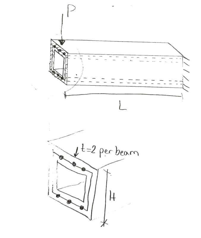
2020_10_05_13.48_Office_Lens_t85tkj.jpg

To me it looks as if the stresses from the outer profile must be transferred to the inner profile through the spot welds, which could reduce the load that the profiles can withstand.
[ul]
[li]What theories are of importance to analyzing this situation? (e.g. Grashoff?)[/li]
[li]Will the spot welds be a limiting factor to the size of P?[/li]
[li]How would you go about analyzing this scenario, if both the displacements and P_yield is of importance?[/li]
[li]How do you calculate the max value of P?[/li]
[/ul]
The scenario left me curious, as I have barely any idea how to answer his question.
 
Replies continue below

Recommended for you

the deflection of the outer tube would apply load to the inner tube.

I'd expect the two tubes behave less than one homogenous tube (t = t1+t2). I suspect they behave like I1+I2, the two tubes would share the load based on their I (well, their EI).

another day in paradise, or is paradise one day closer ?
 
rb1957 : your suspect is correct. Problem already discussed in other threads. If welds are connecting the two tubes all along the length, then you can consider an homogeneous tube (t=t1+t2)
 
Thanks for the help! I will look for the other threads mentioned and relay the information to my friend.
If you have links to the mentioned threads at hand, I would be glad if you qould send them to me.
 
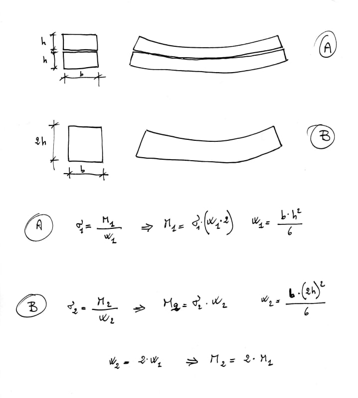
easier for me to show the explaining formulas (case A - tubes fitted inside each other without welds or overlapped without welds is same ; case B - same as previously said but welded all along)

beam_deflection_ct9thc.jpg
 
This beam is a composite beam, if the spot welds are capable of resisting the shear flow, VQ/I, at the interface. For this case, V = P. So the key here is the strength of the spot welds. The rest design checks can then be performed on the composite/built-up section, provided it is a cantilever as shown.
 
To me, it seems kind of iffy to count on spot welds at the end of the beam to resist the entire shear flow.
 

Pls correct me if i am wrong. I understand two rectangular hollow sections fitted into each other . One end fixed to the support while at the free end , the beams are connected to each other with spot welds

We do not know how tightly fitted. That is, will friction develop between two sections?

Assuming lightly fitted, ( say friction will not develop),

In this case there are two allowable loads for P;

İ) The section will behave one homogeneous tube t=t1+t2 for P < (Max. capacity of total 6 spot welds )

İİ) If the spot welds broken at a certain level of P , the beams behave as two separate beams as rb1957 (Aerospace) pointed out.

Note= The shear capacity of 6 spot welds shall be calculated using the shear flow between two beams.
 
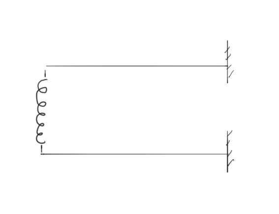
If you assume that the inner tube is free to slip in relation to the outer tube, ie no frictional resistance, then you could model it as two cantilevered beams coupled at the end with a spring representing the spot welds.

Capture_upqwzj.png


My Personal Open Source Structural Applications:

Open Source Structural GitHub Group:
 
@robyengIT that is what I am starting to understand. It is basically equivalent to two beams in parallel, right? Where k is the bending stifness.
[URL unfurl="true"]https://res.cloudinary.com/engineering-com/image/upload/v1601916972/tips/main-qimg-bb078e2de276e2aff620a6288fe17aa3_zt9ict.webp[/url]
By this point I believe this would be the most reliable assumption, as @XR250 pointed out, and is also easy to calculate.
Thank you for all your responses.
 
It is basically equivalent to two beams in parallel, right?

Yes, if the welds are strong enough to resist the shear flow, so the tubes are bind together on both ends to form a built-up shape. For such case, regardless of gap in between, the stresses are proportional as in an integral section. If the welds do not hold, When the gap is closed by the deflection of the outer tube, it becomes a spring between the tubes condition as pointed out by Celt83.
 
Someone please convince me that there is indeed shear flow here.

Say these tubes are lightly fitted (no friction between them) but they are fitted like idealized hollow rectangles say 20x20x2 & 16x16x2. Would there be any theoretical shear flow between the members?

I'm tempted to say no. The I of the combined section equals the I of each section summed and the CL of the sections are the same. You don't gain any stiffness if they're connected versus not.

From a formulaic perspective, wouldn't Q (from VQ/I) be zero here b/c both sections have the same neutral axis?

But I'm open to the fact that I'm wrong in my thinking. Thoughts?
 
@r13 Your last sentence confuses me slightly. If the welds do not hold, why would I have a spring representing their stiffness? If the spot welds do not hold, it is equivalent to them not even being there, right?
 
azcats said:
But I'm open to the fact that I'm wrong in my thinking. Thoughts?

You are right.

Two concentric beams will have exactly the same strains and stresses as two adjacent beams, with the load distributed in proportion to their stiffness, so there would be no slip at the interface even if there was no weld.

Stacked beams are different.

Doug Jenkins
Interactive Design Services
 
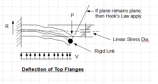
Hope this diagram makes sense. Note, shear flow approaches maximum at the neutral axis, at which Q is maximum.

image_kb6mq8.png
 
nikoD,

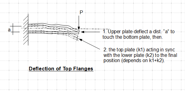
Hope this sketch explains.

image_re27j0.png
 
Correction, in step 2, the final deflection depends on the springs k1 and k2 in series. The numerical addition of k1 and k2 is incorrect.
 
@r13 thanks for clarifying, I get it now.
@azcats and @IDS So I can neglect the spot welds, and it wouldn't even make a difference?
 
I'm tempted to say its I1+I2.

However, I have always been a fan of moving away from an analytical approach and build a scaled down model to test, myth busters style. Its more fun that way.
 
nikoD said:
@azcats and @IDS So I can neglect the spot welds, and it wouldn't even make a difference?

Yes, assuming that the tubes are in contact, or negligible gap.

I1 + I2 for concentric tubes with wall thickness t is exactly equal to I for a single tube with the same external dimensions and wall thickness 2t.

Doug Jenkins
Interactive Design Services
 
Status
Not open for further replies.

Part and Inventory Search

Sponsor