Continue to Site

Eng-Tips is the largest engineering community on the Internet

Intelligent Work Forums for Engineering Professionals

  • Congratulations waross on being selected by the Eng-Tips community for having the most helpful posts in the forums last week. Way to Go!

Tubular Joint RHS to CHS. Out Of Plane Brace Eccentricity. 1

Status
Not open for further replies.

Ussuri

Civil/Environmental
May 7, 2004
1,582
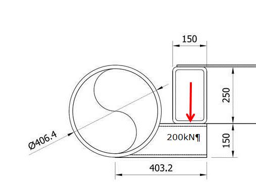
I have a detail (see below) where I have a 250RHS resting on a 150SHS corbel, which is itself attached to a 406CHS.

I am looking at the tubular joint check (RHS brace to CHS chord). I am looking for some guidance into the joint capacity where the incoming brace is eccentric to the chord centreline. I normally use CIDECT for my joint checks. However, CIDECT deals with joints where the centrelines intersect, presumably this is because all the physical testing is based on this arrangement.

API RP2A allows an eccentricity of D/4 (although this is specific for CHS to CHS joints) but offers no guidance if you exceed D/4.

Is anyone aware of any research or guidance on the capacity of tubular joints with an out of plane offset in the incoming brace?

Joint_detail_ytxwgr.jpg
 
Replies continue below

Recommended for you

not sure where your problem is...is it the attachment of the corbel to the 406CHS?...a sketch with the applied loads would help....not aware of any test data on this...
 
There is maybe not a problem. The tubular is a 406OD x 16WT. The SHS is a 150 x 150 x 12.5. When assessed using the CIDECT formula the joints works ok (albeit working fairly hard).

My query relates to the fact the joint capacity design formula from CIDECT assume the brace is positioned central to the chord so the loads are applied in the middle of the chord ring. Hence for the ring bending, the stiffness of the ring either side of the brace is the same.

In this case, because the brace offset the face of the CHS cannot bend equally either side of the brace. The lower compression flange of the SHS frames is transferring load into a tangent point so is very stiff, whereas the top tension flange is applying load close to the middle.

So are the design formulas applicable?

Hence I was looking to see if anyone knew of any background info on this.

Joint_detail_lnxnnr.jpg
 
Can the CHS take the additional bending from the RHS? If you are simply trying to provide an out of plane brace for the section without transferring load, I would provide a plate welded to each member with a vertically slotted hole(s?) to provide the connection between the two. The plate would allow for the CHS to be braced closer to the centerpoint, thus helping out with your CIDECT formulas.
 
 http://files.engineering.com/getfile.aspx?folder=778d756f-4e48-476c-9cf5-5460538ada77&file=CHS_RHS_Brace.pdf
attached are some suggestions...
OPTION A
add rings and analyze rings for applied loads ...superimpose stresses from loading 1 & 2 to obtain max stress in rings.

OPTION B
move corbel to centerline of CHS as OP indicated that there was a solution for this case in CIDECT, then develop conn of SHS to RHS....this conn is less complicated..
ofcourse the CHS should be analyzed for the imposed loads locally and globally, if req'd..
sorry for the attached pages being upside down, although ,if the OP is in Australia, then it should be no problem...
 
 http://files.engineering.com/getfile.aspx?folder=b7f821cd-1a12-470b-8c9c-ed83ecbb71c2&file=HSS_CONN_1-2.pdf
Thanks for the suggestions. Unfortunately the detail will need to remain as is. The corbel is supporting a steel plate roof panel (which is fabricated from RHS and 8mm steel plate) which is removable. I should have clarified this (I implicitly assumed it) when I said corbel. The top of the RHS (and plate) must be level with top of CHS.

SAIL3, Thanks for taking the time to put together a sketch, you have shown the loads carried by ring internal shear forces, Would there also not be a bending component developed by the force couple from the moment?
 
the rings are designed to take care of local circumferential bending in the CHS and ....the CHS should then be checked for the overall applied torsion and longitudinal bending(local & global) due to the applied load P...

I have attached a revised page 1 showing the correct location of P on the rings and it's radial and circumferential components.....
 
 http://files.engineering.com/getfile.aspx?folder=3ae3f139-e703-4b1b-afb2-1e0d91823050&file=HSS_CONN_1-2A.pdf
Status
Not open for further replies.

Part and Inventory Search

Sponsor