Tek-Tips is the largest IT community on the Internet today!

Members share and learn making Tek-Tips Forums the best source of peer-reviewed technical information on the Internet!

  • Congratulations MintJulep on being selected by the Eng-Tips community for having the most helpful posts in the forums last week. Way to Go!

Torx driver tip 5

Status
Not open for further replies.

evosmudge

Industrial
Joined
Oct 6, 2003
Messages
3
Location
US
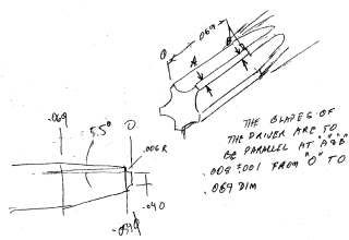
Does anyone know how to extrude the tips of a torx driver? The tip end is narrow and tapers out to the diameter of the rod. The "tips/blades" of the stars are to remain parallel until it reaches the final rod diameter while following the angle of the taper. I've tried extruding the arc at an angle, but it delivers tips/blades that are not at a constant width.

Any help is appreciated.

TORX.jpg
 
evosmudge,

Go and download these from a company called Facom, they have many tools ready to use. You will need to register but it is free.


John H. Dunten, CD
Certified Drafter
 
I'm not sure I understand your requirements: " The 'tips/blades' of the stars are to remain parallel until it reaches the final rod diameter"

If you are modeling this as a traditional torx drive--which is at often illustrated as being comprised of continuously tangent curves--there are no planar "sides" to remain parallel as it tapers.

Are you trying to represent a part similar to those you see forged? Those don't typically have the shape you describe.

I've modeled something similar before (for a machined part), but I don't think it's what you are asking (link)


 http://i47.tinypic.com/4qkmcm.png
The problem is that I think he is asking for the outside diameter of the torx to taper (not just the cuts that form the tines). I cannot understand how you can keep the width of the tines consistent without making some compromise to the shape of the torx--and you can't just loft from one size to another torx since he wants to the width of the tines to stay constant.

I could be misinterpreting his sketch.
 
- CorBlimeyLimey
I tried both the swept-cut and revolved-cut but did not get the results I wanted. Thank you for the suggestion.

- BiPolarMoment
This is to be modeled as a traditional torx driver but with the size of the bit, the paralleled tips are required to make a stronger edge. Also, with a vast amount of screws made by different companies, the taper allows flexibility with their designs.

- takedownca
Thank you for the file. Unfortunately, the tips had to be redesigned as mentioned above.

Fellow Forum members, I was able to figure out a solution after starting the thread. By adding different planes and two arcs/circles at each end following the taper, I used the lofted cut command. This allowed the arc to stay at the same diameter while keeping the edges parallel through the taper. I hope that made sense. Below is a copy of my results. Thank you for all the suggestions.

 
 http://files.engineering.com/getfile.aspx?folder=502fd238-26eb-42a2-bc61-d62a147bba36&file=Torx_taper.SLDPRT
Ah, I see. I couldn't tell from the dwg that the OD tapers. Lofting will work, but FYI, you can do the same thing with an extrude and some construction sketches to get the right direction vector. It uses fewer features and rebuilds quicker, too. Check out the attached filed.
 
 http://files.engineering.com/getfile.aspx?folder=ee2266cf-7ccb-434e-8281-f45d8ec4ddb2&file=Torx_taper2.SLDPRT
Thank you takedownca. I have never tried that approach, but will use that technique from now on.
 
Status
Not open for further replies.

Part and Inventory Search

Sponsor

Back
Top