Continue to Site

Eng-Tips is the largest engineering community on the Internet

Intelligent Work Forums for Engineering Professionals

  • Congratulations cowski on being selected by the Eng-Tips community for having the most helpful posts in the forums last week. Way to Go!

Temporary propping of bridge during demolition

Status
Not open for further replies.

Temporaryworks

Structural
Aug 27, 2017
46
Hi,

I have a question regarding the effect that spacing of temporary propping has on how much load those props attract. To give you some context to the question, please see attached sketch and read below:

- A 6m wide pedestrian bridge spanning 6.5m is supported between an elevated pedestrian concourse and the 1st floor of a building.
- The bridge will be saw cut where the bridge meets the concourse and then the concourse will be demolished. The bridge will be retaining for a while hence the need to isolate and support it.
- I have been tasked with designing temporary propping at the concourse end to take the self-weight of the bridge. On the other side the bridge is still supported by the building, thus the props are only required at one end.
- The bridge is a reinforced concrete one, spanning approx 6.5. It has been formed of two beams approx 0.5m deep x 0.3m wide which do the spanning and then a slab spans the other way between the beams to form the walkway.
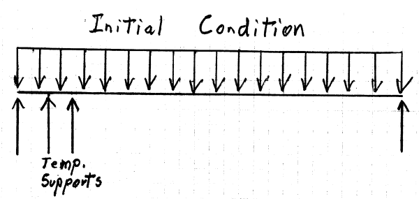
- I plan to prop the beams at the end that requires support with 2no props on each beam - 4no in total.

If I butt the props up together I can assume that they will take half the load each).

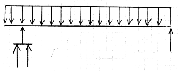
If I then space these props out 500mm from each other so that they can be braced to each other and to the 2no props on the other side to provide stability, can I still assume that they act together? Or will the inside prop take significantly more load (see attached for dims).

I think that that the answer has something to do with the stiffness and the deflected shape of the beam.

Thanks in advance,
Temporaryworks
 
Replies continue below

Recommended for you

I would try using just two props for the gravity load. What did you have in mind for the shores? Trishores? Wide flange columns? In addition to gravity loading, you must provide for lateral stability, so a braced frame bent on that end would be my choice.
 
hookie66 and racookpe1978, thanks both for replying, apologies it has taken me so long to message back, I appreciate your responses.

I have perhaps not made my questions clear enough, so I will try again, please read in conjunction with 2no files as per below links.

I have been asked to use Lahyer scaffolding for propping as that is what the sub-contractor has available. 2no lahyer standards per beam is sufficient to take the vertical load (4no in total). Vertifcal load consists of self weight and a nominal access load.

Once the bridge is cut it is not laterally stable in either direction. To stabilise it along the bridge I have detailed angles bolted between the head of the bridge and the retained building. To stabilise it along the bridge, I have turned the scaffold props in to braced tower frames, the bridge is fixed to the head of the props.

Unless you disagree, I don't have any issues with stability.

My questions is - each scaffold prop is 75% utilised in compression based on each prop taking 25% of the total imposed load in the propping. However, my manager said that the inside props will actually take far more load than the outside props by virtue of them being closer to the span. To clarify - he said that the inside props will support 3m of bridge length and the outside leg (closest to cut line) will support 0.7m of bridge length.

I understand why he has said this but because the props are so close together (400mm) will they not share the load equally?

I would appreciate your thoughts.


Temporaryworks - I see several problems with the proposed plan. Number One is the relatively high loading (75% of allowable on the props). And that value is for ideal, static, steady-state conditions, with an overly optimistic assumption (equal force in all props). Consider that the props have to be positioned and put in compression before the saw cut is made:

Temporary_Supports_-_Initial_Condition-1_ezjxhm.png


Will the compression force in the props be monitored?

As the saw cut is made... what happens? Does one side of the bridge "sag" (binding the saw blade), while the other side remains attached? What is the compression in the props during these dynamic conditions?

What does the Contractor do if (when) the saw blade gets "stuck"? What does his actions do the compression force in the props?

Equal force in all props is practical (for steady-state conditions)... but that is just one issue. Much stronger props should be used because of the unknown forces during demolition:

Temporary_Supports_-_Equal_Loading_qypqxl.png


[idea]
[r2d2]
 
SlideRuleEra,

Thanks for your reply. So in summary, just use heavier duty props. I suppose it would be a good rule of thumb to keep the compression in the props to say 2/3 of working load limit to allow for the unknowns that you mentioned above.

With respect to your comment "Consider that the props have to be positioned and put in compression before the saw cut is made" - the props will just be hand-tightened against the bridge soffit, do you mean that the bridge will sag during cutting and will load the props in a way which is different from the steady state approach that I have assumed?

I think the bridge will not sag anymore that it has currently because it is simply supported in the existing case and that will not change in the temporary case, I am reducing the span if anything? Or did you mean sag because the temporary props would shorten upon loading?

Thanks,

Temporaryworks
 
Temporaryworks - Sorry for the confusion I have caused by using the the word "sag". I am referring to bridge deflection in the third dimension (parallel to the saw cut) as the saw cut is being made. Making that saw cut will be tricky. No matter how the saw cut is done, getting the entire 6.0 meter long saw cut to release cleanly, smoothly (without some impact on the props), and simultaneously from it's existing support probably will not happen. If one of the two beams releases from the support before the other, the saw blade will become locked in the kerf.

Follow the load-path of the props. Will they be supported by a "foundation" that will not deflect under load?
Having the props only hand tight may not be a good idea. That almost guarantees the props will deflect under full load... regardless of their "foundation".

I agree with you that the longitudinal dead load deflection of the the bridge will work in your favor. If all props are (significantly) equally loaded before the saw cut is made, the equal loading on the props should (theoretically) remain unchanged after the saw cut in completed... except there are complications:

1. Before the saw cut, the bridge has simple supports at the ends of the 6.5 meter span. After the saw cut, the bridge has three supports, one at the end and two that allow part of the span to be cantilevered. Don't just "think" about it (and dismiss it), do the math (I did, after making some simplifying assumptions). Load on the support at the end of the span drops from 50% of total load to 44% + of total load. The temporary supports suddenly go from near 0% of total load to 56% + of total load. IMHO, that is a significant event.

2. Temporary construction loading (causing additional longitudinal span deflection) will be supported almost exclusively by the props with shortest (5.6 meter) span. The props with the 6.0 meter span will pick up essentially none of the construction loading.

To me, changing the (theoretical best case) loading on the props from 75% allowable to 67% allowable is trivial. The props need to be much more robust to take the sudden application of full, probably unequal, loading along with potential impact when load application takes place.

[idea]
[r2d2]
 
Thanks SlideRuleEra, that all makes sense and I appreciate the response.
 
A little late to the party, but do your shoring towers allow for a cap beam to divide the load between the two towers under each beam?

----
The name is a long story -- just call me Lo.
 
Lomarandil, if you mean a header beam yes I could do but not sure that that would spread load effectively because it wouldn't be as stiff as the concrete beam it was supporting?
 
You mean because the beams would be running parallel to each other?

Place a contact/bearing plate at midspan of the cap beam (you'll have to check deflections, but I figure 1/2" is probably enough) so that the concrete beam only bears at that location. Then it's just a point load into a cap beam supported by the two towers. That's about as positive of a load distribution as you can get.

----
The name is a long story -- just call me Lo.
 
Yes, of course, that's exactly what I mean.

----
The name is a long story -- just call me Lo.
 
Status
Not open for further replies.

Part and Inventory Search

Sponsor