Navigation
Install the app
How to install the app on iOS
Follow along with the video below to see how to install our site as a web app on your home screen.
Note: This feature may not be available in some browsers.
More options
Style variation
-
Congratulations LittleInch on being selected by the Eng-Tips community for having the most helpful posts in the forums last week. Way to Go!
You are using an out of date browser. It may not display this or other websites correctly.
You should upgrade or use an alternative browser.
You should upgrade or use an alternative browser.
Strut and tie design for pilecap with axial and shear load 4
- Thread starter mte12
- Start date
-
2
- #2
milkshakelake
Structural
CRSI Design Guide for Pile Caps say that strut and tie model is unconservative for pile caps because other modes of failure can control. For that reason, they don't present the strut and tie model. So if one of the biggest authorities on pile caps don't use it, I wouldn't use it. Or theoretically, you could use it and check all the failure modes manually as well.
-
1
- #3
Just Some Nerd
Structural
Curious as I don't have access to that design guide, what sorts of pile cap configurations/failure modes are they referring to? Wondering if that's for smaller scenarios (e.g. 2 or 3 piles) or larger pile cap groupsCRSI Design Guide for Pile Caps say that strut and tie model is unconservative for pile caps because other modes of failure can control.
- Thread starter
- #4
-
1
- #5
HTURKAK
Structural
- Jul 22, 2017
- 3,393
Can you post a sketch ? Is the question is for STM design of pile cap ? Or pedestal ?an example of a strut and tie design for pilecap with axial load as well as shear load at top of pedestal?
My points are ,
-ACI 318 allows the use of STM for deep pile caps .( R13.2.6.5 An example of the application of this provision is a pile cap similar to that shown in Fig. R13.1.1. Pile caps may be designed using a three-dimensional strut-and-tie model satisfying Chapter 23...)
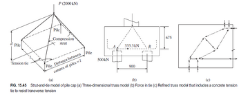
- There are experimental results that clearly indicates that the STM predicts the behaviour of deep pile caps more accurately. There could be modelling problems of the strut elements with a single compression element. The compression force at struts in deep pile caps in general is not the reason for failure by crushing of concrete. But failure occurs after the compression strut splits longitudinally due to transverse tension caused by spreading of the compressive stresses.
- This can be seen with a refined strut-and-tie model as shown in below Fig. 15.45(c) copy and paste from NARAYANAN,
- The use of transversal reinf. will improve the resistance ,
- Other failure modes should also be checked as MILKSHAKELAKE pointed out.

I have attached two documents for STM modelling issues and worked examples.
Attachments
milkshakelake
Structural
The ACI 318 provision HTURKAK mentioned is for allowing S&T analysis for deep pile caps, which is when the top of the pile cap is more than 0.5 times the distance in plan from center of column to center of nearest pile. I think this would apply for most pile caps. Maybe not ones for light piles, like helical piles.
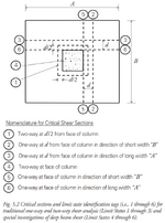
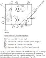
CRSI has the following limit states to check. Some of them are based on the column (limit states 1 to 6) and others at the pile (P1 to P4). Some of them are deep beam shear. I use an enveloped approach with FEM and also checking the limit states.
Source: CRSI Design Guide for Pile Caps first edition.


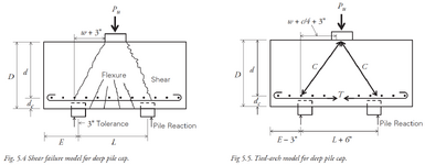
There is also a tied-arch failure mode near the column. CRSI recommends 180 degrees hooks as a precaution against this failure mode. Though in my experience, contractors find it difficult to make these hooks, especially with larger diameter rebar.

Edit: I'm not sure what codes AU uses, but there are spreadsheets published by CRSI. It's not very useful without the CRSI guide, but it's a taste: https://www.crsi.org/supplement-dg-for-pile-caps/
CRSI has the following limit states to check. Some of them are based on the column (limit states 1 to 6) and others at the pile (P1 to P4). Some of them are deep beam shear. I use an enveloped approach with FEM and also checking the limit states.
Source: CRSI Design Guide for Pile Caps first edition.


There is also a tied-arch failure mode near the column. CRSI recommends 180 degrees hooks as a precaution against this failure mode. Though in my experience, contractors find it difficult to make these hooks, especially with larger diameter rebar.

Edit: I'm not sure what codes AU uses, but there are spreadsheets published by CRSI. It's not very useful without the CRSI guide, but it's a taste: https://www.crsi.org/supplement-dg-for-pile-caps/
Similar threads
- Replies
- 3
- Views
- 8K
- Locked
- Question
- Replies
- 3
- Views
- 4K
- Question
- Replies
- 3
- Views
- 9K
- Replies
- 5
- Views
- 2K
- Replies
- 6
- Views
- 8K
