Continue to Site

Eng-Tips is the largest engineering community on the Internet

Intelligent Work Forums for Engineering Professionals

  • Congratulations KootK on being selected by the Eng-Tips community for having the most helpful posts in the forums last week. Way to Go!

Structual behavior of welded steel rings 1

Status
Not open for further replies.

Gymnast

Electrical
Mar 22, 2008
22
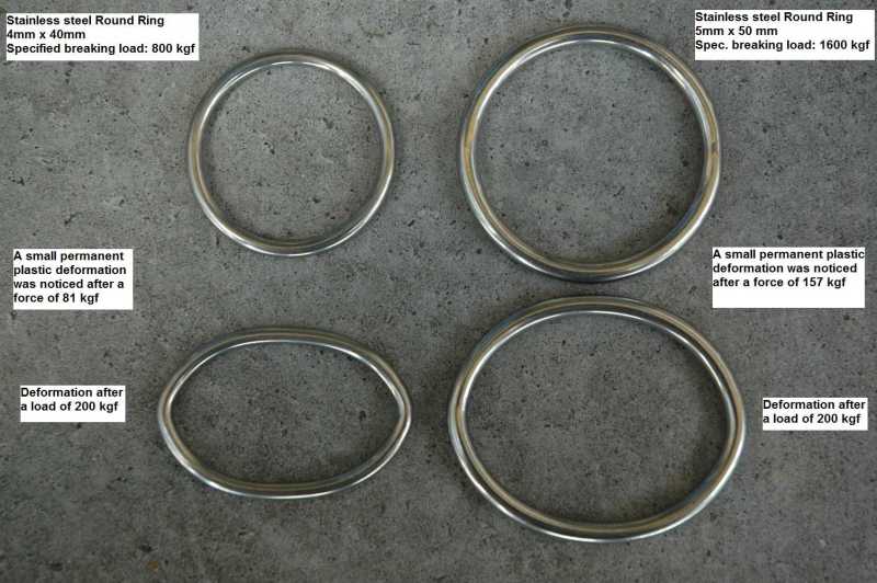
Before I even considered calculating, and for a small project I ordered two kind of steel rings from here:


Some 4 x 40 mm rings and 5 x 50 mm rings, and they have specified breaking strengths of 800 kgf and 1600 kgf.

I decided to make some simple pull testing of the rings, and found, that plastic deformation of the rings occurred at about 10% of the breaking strength. I was surprised by this low level, but I am no structural engineer. But after some simple structural calculations, it appears to me, that this can very well be the case. Actually the plastic deformation might occur at even lower load levels.

The specified breaking strengths from the supplier refer to a completely plastic distorted ring. If we assume two Ø5 steel wires with uniform stress, I can calculated the breaking stress to be 401 MPa.

A very simple calculation for the initial moment for plastic deformation of the thread would be M = 25 mm x F/2 where F is the force applied. Then no moment is applied from "the side". If we assume plastic deformation at 401 MPa then I get F= 394 N or 40 kgf. But I noticed the deformation starting at a force of about 160 kgf.

I have tried to look in Roark's formulas on curved beams, but I have a hard time selecting the right formula.

At what load level can you expect plastic deformation to start at such rings. Please help.

Tested_steel_rings_GS_Products_with_results_yaa0l7.jpg
 
Replies continue below

Recommended for you

Since they list the grade of steel on the website, you should be able to look up the yield stress and the tensile/ultimate stress. For elastic design, you would then find the applied stress by using the applied moment divided by the section modulus. Keep the applied stress under the yield stress and you'll have no plastic deformation. I would start assuming a straight circular cross section beam and find the stresses under a point load and compare them based on your tests. Refine the problem for ring curvature if you're getting large deviations between theoretical and applied.
 
Thanks for reply.

I don't think I get this right.

When I look up the Stainless Steel A4-AISI 316 Marine Grade I get about 600 MPa of tensile stress. If I assume this to be the elastic stress, then I should get plastic deformation just above 60 kgf. But I measure it to be much higher level - about 160 kgf. I calculate W of the wire to be 1.23E-8 m^3.
 
robyengIT, thanks for this very detailed information with many cases.

For this special case I have found a reference with an analytical solution here:

Link

When the wire diameter is low compared to the ring diameter, then the max moment of the wire should be:

M = R x F / pi (robyengIT references says the same: M = 0.318 x R x F)

And R is the mean radius of the ring. When I use 600 MPa elastic strength for the 5 x 50 ring (R=27,5 mm) then I get force to be:

F = stress x W x pi / R = 86 kgf

Then I repeated the pull test with more accurate meassurements to see just a small permanent change of ring local diameter of about 0.2 mm. I noticed this change at a force of 117 kgf for two rings. The rest might be differences in steel elastic strength and other inaccuracies.
 
Gymnast:
If you are actually loading/using these links in tension like you indicate you are testing them, you would be better off to use elliptical shaped links (oblong links?), like chain links. I can’t seem to bring up your attachment, scan it and post it as a pdf attachment. Roark’s book, any number of good Advanced Strength of Materials texts, or Theory of Elasticity texts, several of Timoshenko’s books cover rings, chain links and hooks. Looking at their analysis and design would be instructive. If the deformation is objectionable, a piece of steel bar stock with pin holes at each end might be better at transmitting your tension load.
 
Thanks for the comment dhengr. Actually I use the rings for more purposes and often with more ropes or webbing going in to them. We also use this special hook in our gym to reach attachment points near the ceiling - you may like to know that it exists for other purposes:


So multiple usage, easy access, price and availability is also important using steel rings. I was surprised to learn that the limit for elastic deformation was about 5% of the load specified as the sellers breaking load. I am not a structural engineer, so some parts of Roark's book can take some time for me to grasp. Now I got this problem solved - thanks!
 
I have looked for the solutions for a point load to one side of the ring and a distributed rectangular load to the other side. I cannot find that in Roark's book, but it seems to be twice in the tables from Kittel supplied by robyengIT above.

I find it in the Kittel tables as "load case 2" and later as "load case 1A.8". My problem is, that the table numbers are not the same, and I cannot figure out any difference in the cases.
 
Status
Not open for further replies.

Part and Inventory Search

Sponsor