Continue to Site

Eng-Tips is the largest engineering community on the Internet

Intelligent Work Forums for Engineering Professionals

  • Congratulations The Obturator on being selected by the Eng-Tips community for having the most helpful posts in the forums last week. Way to Go!

Steel Deck Plate as Lateral and/or Torsional Bracing of Beams 3

Status
Not open for further replies.
Replies continue below

Recommended for you

Hello,

I would like to prove that 1/4" deck plate is sufficient lateral/torsional bracing for steel beams.

Bracing Requirements per AISC

I believe a slab or flat metal deck plate would be considered panel bracing. Appendix 6 of the AISC manual and the associated commentary gives the following equations for required stiffness and strength of panel bracing (equations originally come from Fundamentals of Beam Bracing by Joseph Yura attached)

Stiffness: βbr=2*Ni*Ct*Pf*Cd/Φ*Lbr
Strength: Pbr=0.005Mr*Ct*Cd/h0

My question is not on the required limits side, but on the available strength and stiffness of the deck plate.

Question #1) As I understand it beam bracing is predominately needed to prevent twist of the cross section, so should the stiffness snd strength of the deck plate be measured in it's in plane direction (axial stretch/shortening), or should its ability to resist an end rotation be measured?

I'm inclined to believe the stiffness and strength requirements are for an in-plane deck force only, since an in-plane force at the top of the flange would effectively prevent twist of the compression flange, due to its offset location from the N.A. If this is correct the next question is

Question #2) Is the most appropriate method to check the strength and stiffness of a continuous deck plate to check in 1' unit strip widths? Same would go for the connections between the deck and beam compression flange.

Question #3) The beam stiffness equation has a variable Pf, which is the beam compressive flange force. I assume it is conservative to take the full compressive force above the N.A. as My/I+Pc

Any help or conversation is much appreciated. I've seen this question asked on here a couple times, but only for corrugated deck prior to concrete, never for flat plate.

“The most successful people in life are the ones who ask questions. They’re always learning. They’re always growing. They’re always pushing.” Robert Kiyosaki
 
MS said:
Question #1) As I understand it beam bracing is predominately needed to prevent twist of the cross section, so should the stiffness snd strength of the deck plate be measured in it's in plane direction (axial stretch/shortening), or should its ability to resist an end rotation be measured?

I see it the same. In most cases you're relying on the deck as lateral bracing only, not torsional bracing.

MS said:
I'm inclined to believe the stiffness and strength requirements are for an in-plane deck force only, since an in-plane force at the top of the flange would effectively prevent twist of the compression flange, due to its offset location from the N.A.

Agree. It's even better than you're imagining since, for LTB of simple span beams, the center of rotation is not at the neutral axis but, in most cases, substantially below it. Improved lever arm acting on the resistance etc.

MS said:
Question #2) Is the most appropriate method to check the strength and stiffness of a continuous deck plate to check in 1' unit strip widths? Same would go for the connections between the deck and beam compression flange.

1) Just to get the pragmatic stuff out of the way, let's briefly acknowledge that most designers would not even bother to check the strength and stiffness of a 1/4" steel deck as bracing. Rather, they'd just assume it to be adequate in most conventional situations.

2) It's a bit unfortunate that the case of continuous bracing is analytically more complex then that of discrete bracing. You've got this thing at work where, the shorter the length between brace points, the larger is the elastic buckling capacity of the thing between the brace points which makes the brace demand skyrocket. Theoretically, at truly continuous bracing, your required brace force is infinite. This is influenced by whether or not your situation represents point bracing or relative bracing as you're no doubt familiar with from the Yura stuff.

Here's one approach to dealing with this:

a) Figure out how many, hypothetical discrete bracing points would get your beam working as you'd like it to. In some respects, fewer brace points leads to easier to design braces which, for me at least, is a bit counterintuitive.

b) Figure out the bracing strength and stiffness required of [a].

b) Discretize your continuous steel deck into sensible strips at each of the hypothetical, discrete brace point. As far as I know, there's no getting around applying some engineering judgment to this step. I feel that the "brace" ought not be more than about 20% as wide as the space between the hypothetical braces.

d) Run your strength and stiffness calcs as you normally would on the effective brace strip and it's connections. If you get into trouble with buckling etc, maybe give some consideration to load spread with the braces.

MS said:
Question #3) The beam stiffness equation has a variable Pf, which is the beam compressive flange force. I assume it is conservative to take the full compressive force above the N.A. as My/I+Pc

I'd argue that your approach is not just conservative but more theoretically correct than just taking the flange force. The compression in the web above the NA will contribute to the instability demand on the bracing, if only nominally so.
 
@Koot treating the deck plate as discrete bracing is a brilliantly simple method that I should have thought of. In a specific condition I am working I need to brace a 30 foot beam at mid-span only.

I ran through some quick calculations and see that achieving the required stiffness is not an issue as a 1/4" plate at 6' length x 2' width would be many times stiffer than is required to brace a W14 beam. However, the Euler buckling capacity of the plate at this assumed width is only marginally higher than is required by equation A-6-7, which to me either:

1) Challenges the traditional method of assuming that steel deck provides continuous lateral bracing to the beam

or more likely

2) Shows that my assumption of a 2' design width is woefully inadequate

If I used your 20% rule of thumb it would lead to a 4' design width and adequate buckling strength of the plate, but it leaves me wanting a more "solid" determination of the effective width. Perhaps this is a job for a simple numerical model.

I envision that I could perhaps apply a line load of ~12" (or as wide as two screws) on the edge of a flat plate and a run a eigenvalue solution for a rough approximation.

“The most successful people in life are the ones who ask questions. They’re always learning. They’re always growing. They’re always pushing.” Robert Kiyosaki
 
While a continuous bracing treatment is often sub-optimal, I'm also not certain that minimal bracing treatment is optimal. Frankly, I've never looked at it hard enough to know. Perhaps you'd be better of with 1/3 point or 1/4 point bracing? As a fun experiment, I'd like to program something that attempts bracing at varying intervals and plots the resulting brace requirements as a function of that. Retirement project...

The bucking was what I was getting at with my comment about load spread above. And that kind depends on how far apart your nearest support is. If it's 5' away, it's probably reasonable to assume that, when your fictitious brace buckles, it also takes an extra 2' of plate with it on either side at mid-span. This suggests another retirement project: for a plate simply supported on two edges, what is an effective buckling width? Rationally, you'd probably want to consider what happens when the "brace" also has the design loads on it that would lead to the beam being taxed. I'm not sure anybody actually does that though. I wouldn't do it for a girder; maybe some consideration for widely spaced infill beams.
 
All seems sensible and conservative. For what it is worth this is my approach:
-floor joists considered restrained by floor plate though deflection rather than LTB normally dominates max span
-secondary beams supporting floor joists restrained by floor joists
-primary beams restrained from twist by secondary beams
-I conservatively don't assume the floor plate acts as a diaphragm for lateral loads. Lateral loads have their own in plan bracing if required.**
-There is an implicit assumption here that parallel beams won't LTB as a group due to the stiffness of the connections and flooring diaphragm.
(Overall I find deflection generally dominates my designed here rather than ultimate strength or LTB.)


In the industry in which I deal with where there is metal floor plate there is usually a bunch of penetrations and potential for future penetrations. It wouldn't make me sleep well at night relying on flooring as a diaphragm for lateral loads, though in reality would likely be quite sufficient.
 
There's definatey an elegance to the hierarchy described by human909: progressively stouter things being braced by progressively stouter things. That's probably what got us through a century of braced steel design not paying much attention to the bracing
 
The old British code required 2.5% of the maximum flange force applied as a UDL to the continuous bracing over the full beam length, ie the total load on the bracing plate = 0.025 * flange force. The Australian code requires this load multiplied by the number of discrete restraints that would be required. For braces that are loaded axially as in this case, it is usually the strength requirement that governs over stiffness so there is no stiffness requirement given.

Yura has a report out there that covers continuous bracing: "Bracing of Steel Beams in Bridges". I haven't fully digested it but it may be quicker for those of you who understand the American requirements fluently. It seems though that you can work out the discrete bracing requirements based on two or more discrete braces, sum them (strength or stiffness as appropriate) then apply as a UDL/stiffness to the whole span. This takes away the requirements to make a judgment on the effective width, and reflects the Australian requirement in that regard.

 
I checked out steveh49's reference which can be found here: Link. He does the reverse of my procedure and treats all LTB bracing as continuous, converting point bracing to equivalent continuous.

C01_wr4bvy.jpg
 
KootK, what did you make of the strength requirement for continuous bracing in that report? It seemed to me that it wasn't addressed, despite the stiffness requirement being stated in terms of continuous stiffness. It just seems to revert to 0.8% of flange force per discrete brace, with no discussion of effective width for continuous bracing.


Changing subject, I did spot this nugget in section 1.5 which seems relevant to that long discussion 1.5 years ago about the Australian code's methodology of equating lateral bracing to full restraint of the cross section:

"As a simply supported beam buckles, the lateral deflection of the tension flange is usually small when compared with that of the compression flange. Such a beam is considered to be braced at a point when lateral displacement of the compression flange is prevented since twist of the cross section is also restricted." [Emphasis on simply supported beam is by me.]
 
steveh49 said:
KootK, what did you make of the strength requirement for continuous bracing in that report?

I can't claim to have read the document front to back but, based on my scan of it, I didn't see a continuous bracing strength requirement either. Intuitively, I feel that one could use the equations that allow one to interchange discrete bracing stiffness with continuous bracing stiffness to smear out the strength requirement in a consistent fashion (k/in).

Yura said:
As a simply supported beam buckles...

Interesting. This raises what I find to be an interesting point about the development of knowledge in our space.

There are times in the deep dive threads here where I get the sense that we're actually discovering new insight rather than just sorting out the details of established theory for ourselves. In those cases, it seems to me that there are three possibilities:

1) We're correct and have discovered something new. This makes me sound like and egomaniac, I know.

2) We're wrong and just not that smart.

3) We're correct and simply haven't encountered these insights before because the wickedly smart theoreticians out there (Yura, Trahair) see this stuff as obvious, fundamental, and generally not worthy of explicit discussion.

Both the fly bracing thread and the recent shear flow thread feel like examples of this for me. With respect to the shear flow thread:

1) I've been pitching that reinforcement hanger force / end moment for about five years here and this month was my first real nibble. Most of that's been in reference to the reinforcement of wood members.

2) I've reviewed a LOT of documents on member reinforcing trying to find evidence of the hanger force and end moment concepts. I've not seen it come up once, anywhere. If somebody else has, I'd love to hear of it.
 
KootK said:
We're correct and simply haven't encountered these insights before... I've reviewed a LOT of documents on member reinforcing trying to find evidence of the hanger force and end moment concepts. I've not seen it come up once, anywhere. If somebody else has, I'd love to hear of it.

I think the lateral bracing of one flange when there's contraflexure was probably a lesson for a few of the Australian engineers on that discussion - or at least me. The issue doesn't seem to get much discussion and of course our first thought is to meet code requirements. It's not new though as we know Yura has published articles about it and I now know that the British code had an appendix covering it as far back as 1990.

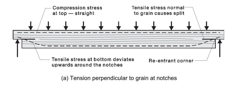
For the hanger force and end moment, someone must have looked at it as it would be the starting point for the timber notch fracture mechanics. For example, something like the hanger force is shown indicatively in a timber design handbook published by Standards Australia (below), and I think it is intuitive if you assume that the stress in the reinforcement develops fairly quickly as per the other discussion.

NotchVertForce_drwnuw.jpg
 
I left my copy of the Guide to Stability Design Criteria of Metal Structures 5th Ed (which is the superior edition, in my opinion) in the states. But I seem to remember that it addressed the continuous bracing topic in more detail.

Another analogy to consider that can be useful in these cases -- discretizing the deck plate as batten plates resisting relative lateral curvatures between the braced beams (as created by top flange buckling) through plate shear.

----
just call me Lo.
 
Status
Not open for further replies.

Part and Inventory Search

Sponsor