Continue to Site

Eng-Tips is the largest engineering community on the Internet

Intelligent Work Forums for Engineering Professionals

  • Congratulations waross on being selected by the Eng-Tips community for having the most helpful posts in the forums last week. Way to Go!

Sloppy Tolerances 4

Status
Not open for further replies.

drawoh

Mechanical
Oct 1, 2002
8,960
See thread404-467338.

What do the shops do when they receive drawings with super sloppy tolerances? I have never gone this overboard, but I do issue sloppy stuff, particularly profile tolerances. My assumption is that the vendor has a standard process with an anticipated set of tolerances. If that is well within the tolerances called up on the drawing, he will use his standard process. If the tolerance is too tight, then either he cannot do the part, or he must do some trickier, more expensive process.

It logically follows that if I change perhaps a machining tolerance from [±]0.5mm to [±]1.5mm, it will no effect on cost, since there is no way for a machinist to take advantage of it.

Are these reasonable assumptions?

Assume you trust the drafter's work.

--
JHG
 
Replies continue below

Recommended for you

I have seen a different peculiar behavior in a couple of different ways.

In one case a nominal dimension was seeing a good sized shift; it turned out that it didn't matter so much as long as it was going to be consistent across the production run as other parts had not been made and could be changed. Since this was a casting we wrote a change to the drawing. Unfortunately this got to the pattern shop - they "fixed" the pattern and then the new parts were out. We let them know that they were going to eat the new, discrepant parts. They agreed and changed the pattern back.

In other cases, many, many cases, parts come in, say 0.005 to 0.010 out on say a 0.060 tolerance. So we look at inspection records for mating parts, see that they are much better than required, issue changes to tighten those up and loosen those on the discrepant parts and boom. The parts made with the new change are again 0.005 to 0.010 out. Why? With the larger zone they shifted production to crappier machines.

While I have seen most suppliers produce parts far closer than the drawing requires, it's those who are outstanding in their ability to really absorb a large amount of engineering follow up, only to toss it in the garbage and do what they want, that surprise me.

Unfortunately a number of times it turns out that the large tolerances that are applied are simply too large; this is a factor that isn't seen until a new supplier comes in, sometimes years later, and all of a sudden, with no change to the design, the assembly/system no longer works.

Fun on both sides of the paper.
 
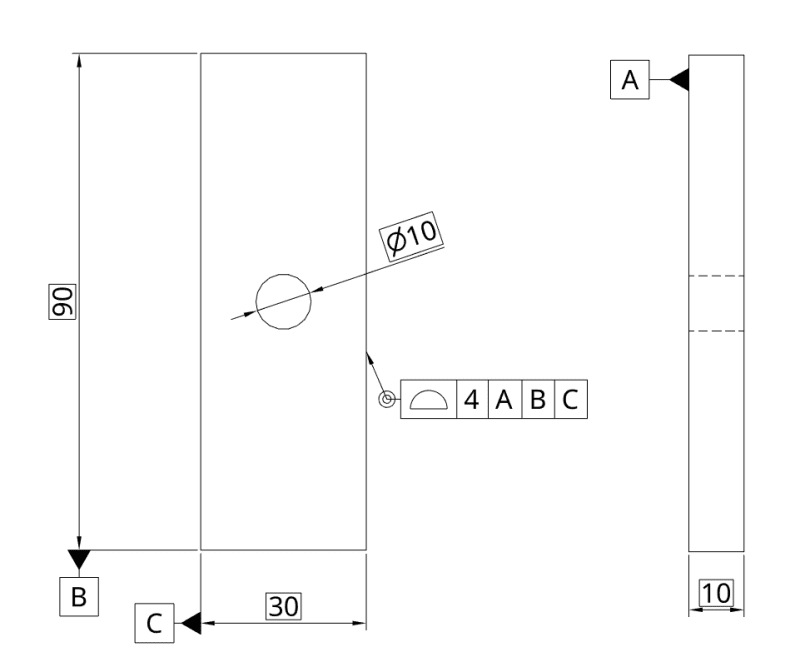
While I briefly looked at the topic drawoh linked, I questioned myself with possible solution, at least if it's ISO. (newer ASME doesn't like symmetries anymore, someone said)
Well, it's more like half-guess from me, mostly because I'm not sure if that "all-over" even covers the hole also?
Screenshot_20200502_215722_y5q3kz.png
 
cr7.... Yes, "all over" literally means all over (unless otherwise specified). So in your drawing you could even do away with the three datums and just have that all-over profile of 4 mm (you'd also need to know the Theoretically Exact Dimensions for the hole's location).

John-Paul Belanger
Certified Sr. GD&T Professional
Geometric Learning Systems
 
Belanger said:
... So in your drawing you could even do away with the three datums and just have that all-over profile of 4 mm (you'd also need to know the Theoretically Exact Dimensions for the hole's location).
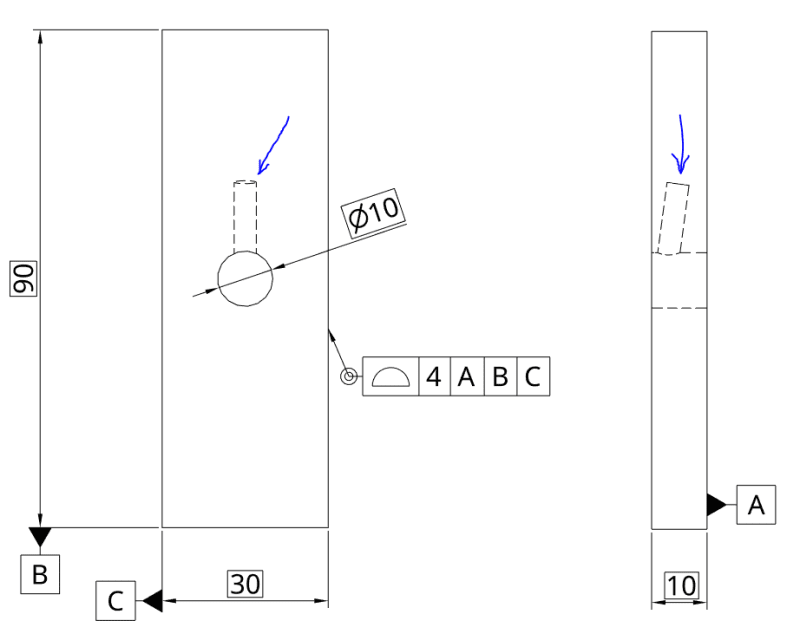
Thank you JP. Would all over cover also the blind cylindrical pocket I added?
allover-pocket_wiea1f.png

I'm primarily interested if ISO allows it, but I'll assume that case isn't any different in ASME. (except for the symmetries)
 
Think of it this way: If you dunk that part into a tub of water, anything that comes out wet will be toleranced. So yes, I would interpret it as covering that extra pocket.

John-Paul Belanger
Certified Sr. GD&T Professional
Geometric Learning Systems
 
cr7, I think all over is more appropriate without datum references. The three datums in your drawing, I believe they contribute nothing to the geometrical specification and there is half the tolerance zone available for datum feature A.
 
In my job, I come across nonsense all the time in feature tolerances and GD&T misapplication. Generally, we abide by the rule, "The customer is always right". If their tolerances and/or scheme make no sense, we leave them alone and do the best we can with our internal processing to achieve those or better. Some of what we see is laughable, to say the least.
 
The thing I hate is when I add any GD&T, sometimes I'm told to take it off. Very few understand it, so remove it. Some think it adds cost to the part.
Then, they change the tolerances on every dim to be very tight! Why? Because it's been that way for 50+ years!
I'm tired of arguing for it! [banghead]

ctopher, CSWP
SolidWorks '17
ctophers home
SolidWorks Legion
 
Burunduk said:
, I think all over is more appropriate without datum references.
I was thinking of "how would I measure this" with this drawing, but I can agree with what you are saying.

Burunduk said:
and there is half the tolerance zone available for datum feature A.
Sorry, can't see how that would be. Can you elaborate?
 
cr7,

Just to throw in a reference as I recently discussed this, the effect on both FOS and non-FOS toleranced features which are also referenced as their own datum features (I like to call this self-referencing) was discussed on another thread with similar callout (all-around though instead of all-over, the concept can be extrapolated).


This of course assumes an ASME interpretation (and is codified in the latest 2018 version). I'm not sure what the ISO practice is for such a reference, however it may be similar.
 
Thank you @chez311. After briefly reading through thread of which link you provided, I get it. (I imagine it like: if your datum is "sitting" on outermost points, there of course will be no more points in that direction, so it makes half of tolerance there ever "empty").
Which makes a lot of difference if I would put that datum A on a symmetry plane. (or more like symmetry of planes, I know, my expression of terms might be off by a lot)
 
chez311,

A crude rule of thumb is that tooling should be about ten times the accuracy of whatever they are producing or measuring. This really ought to go for datum features. If I were doing something like this, I would consider datum targets. I understand this is fairly standard practise for castings.

--
JHG
 
cr7,

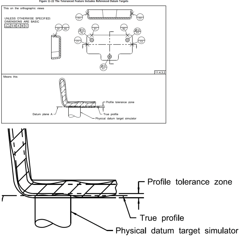
The gist of it is essentially a planar datum feature simulator is coincident with the true profile. For an equally disposed profile tolerance, where the tolerance is equally disposed on either side of the true profile, only half the tolerance zone is usable since only half is on the usable side of the simulator where the part material is. For a unilateral profile tolerance the entire zone is available since the entire zone is on the usable side of the simulator/true profile.

drawoh,

Yes I would agree this is more common with datum targets on castings/molds. In that case since the simulator only contacts a point/line/limited area the portions between the targets may utilize the entire zone while the localized portions which contact the simulator are coincident with the true profile. See Y14.5-2018 fig 11-22.

fig_11-22_fyupm5.png
 
Status
Not open for further replies.

Part and Inventory Search

Sponsor