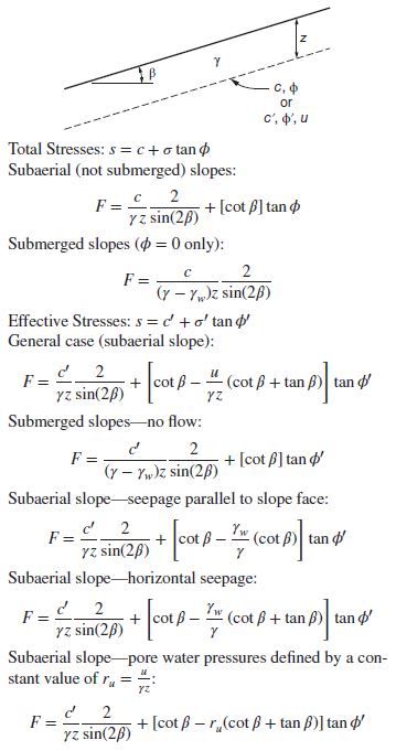
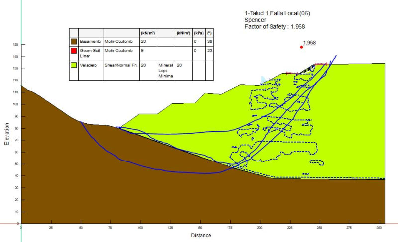
Continue to Site

Eng-Tips is the largest engineering community on the Internet

Intelligent Work Forums for Engineering Professionals

  • Congratulations cowski on being selected by the Eng-Tips community for having the most helpful posts in the forums last week. Way to Go!

Slope Stability during watering - SEEP/W and SLOPE/W 2

Status
Not open for further replies.

abanqueri

Geotechnical
Jan 29, 2019
3
Hi!

I'm dealing with a problem in SEEP/W. I'm actually working on a stacking pile in a leaching valley. The thing is I can't reach an stable flux through the soil. I've been trying with a lot of different models but I don't know were the issue is. The stacking pile has a cross flux due to the solution which has to go to the process plant downstream. It has been modelated with with a boundary condition as a 1m Water Pressure Head. 1m is supposed to be the level of the solution at the bottom of the pile. The watering is 0,072 m/day, and probably the main problem is in the definition of the both matric suction, Volumetric water content and hydraulic conductivity.

After this analysis, I have to evaluate the slope stability. The main thing here is the program interpret there is ponded water in the surface due to something I can't discover. So that This interferes in the SLOPE/W I think and the Factors of Safety doesn't seem to be well estimated.

I attach this file. You can se what I'm saying in the image below.

If you could know something about this problem, I would appreciate a lot.

Thank you!

 
Replies continue below

Recommended for you

I am not familiar with leaching valleys, but I am familiar with SEEP/W. First thing there is no outlet to drain or atmosphere. Second why are you only putting a flux rate on portions of the slope and not the flat benches or on top, how is that being built. Your initial water table is 1 m from the flat base and part way up a 3H:1V slope, water will not follow a 3H:1V slope in sands. In your transient analysis you still have the initial 1 m boundary condition on, this should be off as it is stoping the water from merging.

In your SLOPE/W you are trying to figure out if a 2H:1V slope that is 10 m high is stable in an overall 4H:1V slope using 33.8 as a friction angle. This can be done with infinite slope analysis as below from Duncan's book or stability charts. For a real slope failure you need to consider the failure interacts with the phreatic surface, slips on the geosynthetic, or loose foundation materials.

Duncan_Infinite_slope_bdiqe2.jpg


The first stage of site investigation is desktop and it informs the engineer of the anticipated subsurface conditions. By precluding the site investigation the design engineer cannot accept any responsibility for providing a safe and economical design.
 
Thank you a lot for answering

I understand your point that's why I'm gonna give some details answering your explanations:

1- First thing there is no outlet to drain or atmosphere: this is due to I'm analizing a 2D model while in real we have a 3D flow. It's supposed the flux should go to the bottom and then across the section, I mean out of the screen because there is a drainage pipeline. To do that, We model as a boundary condition with water preesure head = 1m to avoid the level of water increases. This would be the maximum level the water table can reach or less but not higher.

2- Second why are you only putting a flux rate on portions of the slope and not the flat benches or on top, how is that being built: this is because in the real problem only the slopes are being watering and not another areas.

3 - Your initial water table is 1 m from the flat base and part way up a 3H:1V slope, water will not follow a 3H:1V slope in sands. In your transient analysis you still have the initial 1 m boundary condition on, this should be off as it is stoping the water from merging: I have this condition activated in the bottom due to what I explain before, I need the water table not increase more than 1m so all flow which reach that level "dissappear" in the model interpreting the flux is flowing through the screen. Why the water table and boundary condition from those points at the bottom? Because we think it should be the area with some level of water.

4- In your SLOPE/W you are trying to figure out if a 2H:1V slope that is 10 m high is stable in an overall 4H:1V slope using 33.8 as a friction angle. This can be done with infinite slope analysis as below from Duncan's book or stability charts. For a real slope failure you need to consider the failure interacts with the phreatic surface, slips on the geosynthetic, or loose foundation materials: I think I don't understand here your point very well. What I think I'm doing in SLOPE/W is to analize the failures in different steps where the phreatic surface is not the same in every case.
 
For a drainage layer in and out of the page this needs to be another material that is saturated only, and have zero head boundary condition. See tutorial
By watering your slopes I don't see how you will have any real increase in water table if the drains are working and someone is monitoring the situation. As time goes by you you can really do is reduce the matric suction or negative pore pressures which you can just set in a steady state analysis to cap out at any value.

For your slope analysis you should be considering these types of failure planes for the entire slope, the infinite slope and stability charts will tell you if the benches will fail.
Failure_h3mckq.jpg


The first stage of site investigation is desktop and it informs the engineer of the anticipated subsurface conditions. By precluding the site investigation the design engineer cannot accept any responsibility for providing a safe and economical design.
 
Thank you a lot for all your recommendations.

Here I go with the last question, is there any possibility to avoid the pwp condition over the slope. Because I'm almost sure this is giving wrong results during transient analysis and so the stability ones.

image_gndljn.png
 
Status
Not open for further replies.

Part and Inventory Search

Sponsor