Continue to Site

Eng-Tips is the largest engineering community on the Internet

Intelligent Work Forums for Engineering Professionals

  • Congratulations KootK on being selected by the Eng-Tips community for having the most helpful posts in the forums last week. Way to Go!

Slab on Grade Relief Port Locations

Status
Not open for further replies.

KootK

Structural
Oct 16, 2001
18,611
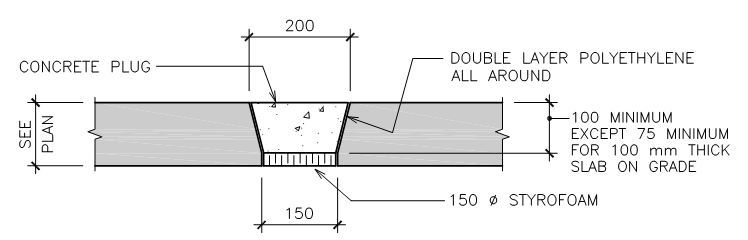
I've got a slab on grade that may see some water coming up from the bottom at some point in the future. Rather than tank the basement, we'll have these nifty relief ports installed in the slab on grade. My questions:

1) How should I space these things?

2) Are there certain locations that are better than others? I've been assuming that near bu not at floor drains (low points) would be good. And I'm drying to keep them out of the drive isles for durability.

Anyhow, I'll take whatever recommendations anyone cares to offer. I've run this by both my mechanical and geotechnial consultants and the responses so far have been less that inspiring.

Capture_h09vig.jpg


I like to debate structural engineering theory -- a lot. If I challenge you on something, know that I'm doing so because I respect your opinion enough to either change it or adopt it.
 
Replies continue below

Recommended for you

How are these intended to work. Is the concrete plug supposed to be removed to allow the water to come up the hole? or is it intended to seep at the joint between the slab and plug?

I would think spacing and locations should be discussed concurrently with both the mech and geo guys as it would be a function of the amount of water expected, the flow rate through this relief port etc.
 
jayrod said:
or is it intended to seep at the joint between the slab and plug?

The valve's supposed to pop out under some amount of buoyant pressure that would be seemingly impossible to calculate accurately.

jayrod said:
I would think spacing and locations should be discussed concurrently with both the mech and geo guys as it would be a function of the amount of water expected, the flow rate through this relief port etc.

As logical as that sounds, it's invariably fruitless. It's about like trying to get other consultants to participate in the dreaded weeping tile discussion.

TME said:
This is the first I've ever heard of these.

Commonly used in my area for "by the river" projects. In theory, there's to be 750 gallons per minute flowing through the basement. And that value was reduced five fold post begging. Basement should probably be tanked if we really expect all that wah-wah.

I like to debate structural engineering theory -- a lot. If I challenge you on something, know that I'm doing so because I respect your opinion enough to either change it or adopt it.
 
These look like "homemade" pressure relief valves. We used to use commercially available pressure relief valves that would pop up at a specified uplift pressure. We used these on wastewater tanks and swimming pools. I cannot remember the name of the manufacturer since it was such a long time ago.

Spacing was always a guess since we could not get info from our geotech (although they should have the ability to calculate required pressures).
 
Thanks for the advice guys. At minimum, are we in agreement that the ports ought to be located at SOG low points?

I like to debate structural engineering theory -- a lot. If I challenge you on something, know that I'm doing so because I respect your opinion enough to either change it or adopt it.
 
I agree with jike. Pressure relief valves are common for preventing uplift in swimming pools, so why not just use a commercially available product?

You would have to install the swimming pool relief valves in boxes, probably the drainage pits.
 
hokie said:
so why not just use a commercially available product?

Because this is what's commonly done in my locale. Now let's focus and help KootK with the questions that were asked:

1) Spacing

2) Preferred locations.

I like to debate structural engineering theory -- a lot. If I challenge you on something, know that I'm doing so because I respect your opinion enough to either change it or adopt it.
 
Definitely at the low points as the water has to get back out once the pressure subsides and the water level drops.

I also think a ten foot grid in addition to that would work well.

Mike McCann, PE, SE (WA)


Sounds like a contractor's answer. "That's the way we always do it." But I think I answered your question. You should have one in each floor drain.
 
If you have floor drains in this basement, can you also have an underdrain system, with perforated collector pipes, which lead either to a sump, or to daylight? We designed a stamping-press pit with a "floating" base slab, and an underdrain system which worked great.
Dave

Thaidavid
 
hokie said:
Sounds like a contractor's answer. "That's the way we always do it."

It really does. Let's not kid ourselves though: precedent underpins the bulk of human achievement. Were I raised by wolves, I'd likely not have figured out fork technology yet alone hydrostatic relief ports.

hokie said:
You should have one in each floor drain.

This was my guess too. First pass was 4' away from all of the floor drains. Getotech came back with some guidance to the the tune of about twice this much, a little closer to Mike's recommendation. It forced me to put a few in drive isles which I was trying to avoid, rightly or wrongly.

thaidavid said:
If you have floor drains in this basement, can you also have an underdrain system, with perforated collector pipes, which lead either to a sump, or to daylight?

Yes, we have exactly this in addition to everything else. Our sump is 2m x 4.5m x 2m deep. It's rough as we're between two existing basements and it's messing with footing elevations pretty badly.

I like to debate structural engineering theory -- a lot. If I challenge you on something, know that I'm doing so because I respect your opinion enough to either change it or adopt it.
 
Status
Not open for further replies.

Part and Inventory Search

Sponsor