Tygra_1983
Student
Hi there,
I am trying to calculate the deflection of a moment frame made up with a shear truss.
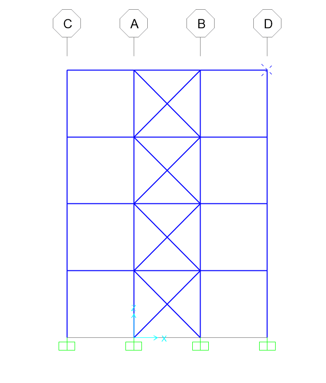
Each bay is 3 metres, so total height is 12 metres. I am using a static horizontal load of 10000 N/m.
I am modelling it as a cantilever beam using stiffness 'K' as (8*E*I)/L^4
I need to find the second moment area of the structure. For the shear truss alone I get the correct deflection. In the literature I have found that the second moment of area is 0.9*(2*(A*1.5^2)). A is the cross-sectional area of the column, 1.5 is the distance in metres from the neutral axis. Using this I get the correct answer. However, when I add unbraced bays to each side I do not.
I guessed that the new second moment area of the total structure is 0.9*(2*(A*1.5^2)) + 2*(A*4.5^2), but I don't get the correct answer from this.
So, Could somebody please tell me what the second moment of area for this structure is, please?
Best wishes
I am trying to calculate the deflection of a moment frame made up with a shear truss.
Each bay is 3 metres, so total height is 12 metres. I am using a static horizontal load of 10000 N/m.
I am modelling it as a cantilever beam using stiffness 'K' as (8*E*I)/L^4
I need to find the second moment area of the structure. For the shear truss alone I get the correct deflection. In the literature I have found that the second moment of area is 0.9*(2*(A*1.5^2)). A is the cross-sectional area of the column, 1.5 is the distance in metres from the neutral axis. Using this I get the correct answer. However, when I add unbraced bays to each side I do not.
I guessed that the new second moment area of the total structure is 0.9*(2*(A*1.5^2)) + 2*(A*4.5^2), but I don't get the correct answer from this.
So, Could somebody please tell me what the second moment of area for this structure is, please?
Best wishes