ModulusCT
Mechanical
- Nov 13, 2006
- 212
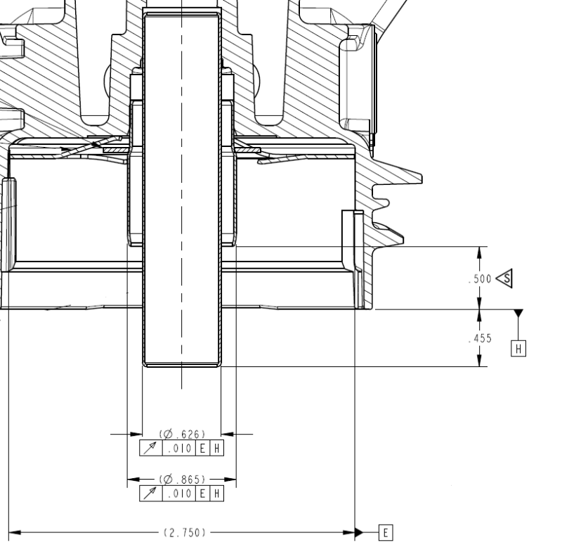
So, please if you will, see the first image attached below. We're looking at a misguided attempt to control 3 separate parts which are mated together (Press fit) and need to be mated with other coaxial parts. The two inner shafts you see are meant to mate with two separate grommets. Because of this, runout is being used (only locally mind you, at 1.20 and .236 - how we're supposed to know this for sure I have no idea - I guess datum targets are not understood here).
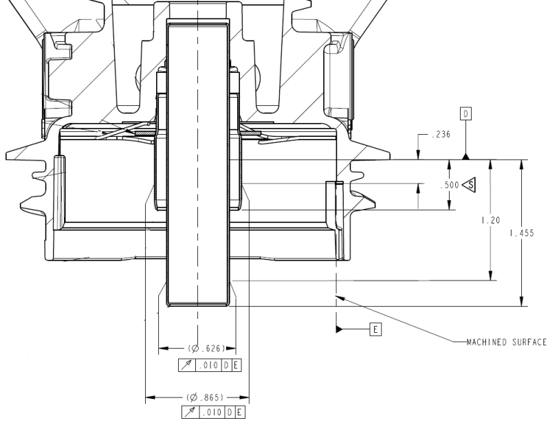
Now, the point is to insure that the two shafts, once pressed into the mating part are perpendicular enough, to datum feature D to insure assembly and proper functioning of the mating seals, which you cannot see in these pictures. I guess I'm wondering why perpendicularity isn't used instead?? The circularity of the part should be controlled at the part detail level to insure proper fit and function.
Datum D is a fiction. This is a cast part, and so, there is no flat surface for datum simulator D to sit on. No, someone would have to make contact with the edge of that feature somehow to simulate D. I'd rather use the bottom of the cast part.
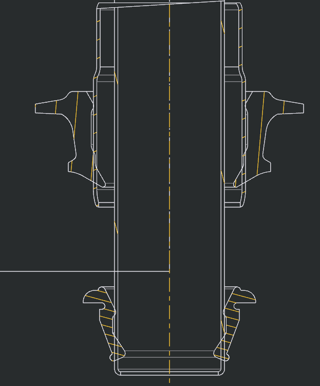
If runout is OK to use here, I believe the implementation is off. I don't think you can point to a single spot and say only measure runout there. I believe it should look something more like the second picture I've included.
Please, your thoughts. And I'm sorry for any gaps in my understanding of these parts or what was originally intended with the first drawing. I've asked, and I get the good old "it's always been like that" as a justification. That, and I've only been here a month and a half. I was told when hired that they needed my help with their GD&T... Uhh, yes.
Please, please, please, use the correct terms!They're Datum Features NOT DATUMS!!! AAAAAHAHAHAHHAHAHAHHAAAAA" -- Don Day
Now, the point is to insure that the two shafts, once pressed into the mating part are perpendicular enough, to datum feature D to insure assembly and proper functioning of the mating seals, which you cannot see in these pictures. I guess I'm wondering why perpendicularity isn't used instead?? The circularity of the part should be controlled at the part detail level to insure proper fit and function.
Datum D is a fiction. This is a cast part, and so, there is no flat surface for datum simulator D to sit on. No, someone would have to make contact with the edge of that feature somehow to simulate D. I'd rather use the bottom of the cast part.
If runout is OK to use here, I believe the implementation is off. I don't think you can point to a single spot and say only measure runout there. I believe it should look something more like the second picture I've included.
Please, your thoughts. And I'm sorry for any gaps in my understanding of these parts or what was originally intended with the first drawing. I've asked, and I get the good old "it's always been like that" as a justification. That, and I've only been here a month and a half. I was told when hired that they needed my help with their GD&T... Uhh, yes.
Please, please, please, use the correct terms!They're Datum Features NOT DATUMS!!! AAAAAHAHAHAHHAHAHAHHAAAAA" -- Don Day