Continue to Site

Eng-Tips is the largest engineering community on the Internet

Intelligent Work Forums for Engineering Professionals

  • Congratulations waross on being selected by the Eng-Tips community for having the most helpful posts in the forums last week. Way to Go!

Round part Datum B center axis DOF removed

Status
Not open for further replies.

sendithard

Industrial
Aug 26, 2021
186
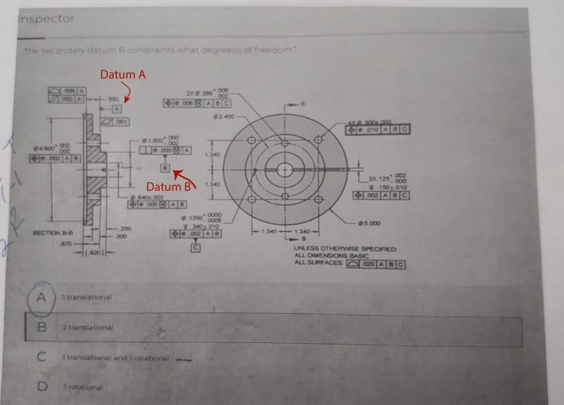
I'm 0% sure my answer to the below question is correct, but at least I have some reasoning behind it stated below.... I sincerely appreciate everyone's help as I know this is fundamentals for some of you. Below, is a simple part and it appears Datum B is a center axis.

The question is how many degrees of freedom does Datum B constrain. From my understanding of 3Ddaves and other previous replies it doesn't matter where you slap this part down on datum A. Where ever you chose to slap it down that is the origin of choice(if you will) and because you have just place the part on datum A, perhaps on a pin on that surface, all the other features are constrained to it. So in theory although you can move this part all over the world on the infinite datum A plane, it is in theory located where ever you drop it and therefore has a x and y translation confinement.

If my thinking it correct, I would choose answer B. Datum B constrains 2 translational movements. Am I thinking right or wrong?....thanks for help. This is from a test that I didn't take and the correct answers are not given so the highlighted answer isn't necessarily correct.
datumBB_gvpc6y.jpg
 
Replies continue below

Recommended for you

I know this might sound like a dumb question, but do cylindrical parts made on a lathe even start out with the same 6 DOF that square parts made on a mill do?
 
sendithard,

do cylindrical parts made on a lathe even start out with the same 6 DOF that square parts made on a mill do?
The shape of the part and how its made do not affect DOF constraint. Geometry and precedence (and potentially how its specified, ie: customized DRF, translation modifier, etc..) of the specified Datum Features is what affects DOF constraint.

It seems like theres a bit of a paradigm shift you may be struggling with. I get it, I remember a having a similar issue - once I overcame that hurdle everything just started to "click".

A simple answer - yes, B constrains 2 translational DOF [x,y].

A point of nitpicking - we don't place parts on Datums. Datums are theoretical, imaginary constructs (perfect points/lines/planes) which are generated from our Datum Feature Simulators*. Simulator/Datum Feature interaction constrains DOF. Focusing on the actual part/simulator interaction is much more important to me than any discussion of theoretical geometry.

I'll attempt a simple explanation/example instead of diving too much deeper into fine details. This is just me trying to take a stab at prompting that paradigm shift. Imagine a gauge which consists of a flat plate with hole in it - the flat portion is your Datum Feature Simulator corresponding to Datum Feature A, the hole being the Datum Feature Simulator for Datum Feature B. The simulator for A simulates only a portion of an infinite plane so the hole for B can be anywhere on that flat plane - obviously with real world gauges we deal with the finite not the infinite so we have to choose some finite sized plate large enough to simulate A and machine a hole somewhere arbitrary on that plate to simulate B. Since A does not constrain [x] or [y]** t doesn't actually matter where we put the hole for B provided its not somewhere on the edges so we get a complete cylindrical feature and leave enough surface area to contact the entire Datum Feature A, and is oriented perpendicular to A (since A constrains [u,v]). Now when we place the part on the gauge the simulator for B constrains the part in [x,y] so the part cannot translate in these directions relative to the simulator.

That wasn't so short or simple, but hopefully it helps?

*or TGC's in 2018, same (similar) concept, but slightly more abstract.

**its a different story if we were talking about a tertiary Datum Feature constraining [w] where [x,y] were already constrained. In this case it still wouldn't matter where B is, but it of course would matter for C.
 
Thanks. I'm improving but do agree with your analysis where I'm at.

What I am not fully understanding is when and why an axis datum stops x,y translation. The reason for my confusion is if I measure this part on a surface plate by hand I would put a pin tightly fit in the center hole to measue C hole but it wouldn't matter where I placed it on the plate so xy isn't constrained there.

On the other hand if I put a pin thru B on the CMM machine datum B axis now has a definitive x,y.

So there lies my confusion. We define B as a datum but does B really need a set x,y location?

Then I look at C and I know it defines where the hole is, but does it constrain Z rotation? I tend to think so since B confined location so should C, but again if rotate the part 10 deg all the holes will still be proper to Datum B.

I hope I explained some of my issues correctly. I am struggling with axis and round features. Square parts with side features as datums are much easier to grasp.
 
What I am not fully understanding is when and why an axis datum stops x,y translation.

If it can, and it hasn't already been constrained by a higher order datum feature (and has not been modified by a customized DRF or translation modifier), then it does. This is often referred to as the "can, may, must rule" - ie: if a datum feature can constrain certain DOF by its geometry/type, and it may (not constrained by higher order datum features and no customized DRF/tranlsation modifier/etc..), then it must.

If we use your example, A already constrains [z,u,v]. B CAN constrain [x,y,u,v] however it only MAY constrain [x,y] since [u,v] is already constrained by A. Since there are no customized DRF or translation modifiers, then it MUST constrain [x,y].

The reason for my confusion is if I measure this part on a surface plate by hand I would put a pin tightly fit in the center hole to measue C hole but it wouldn't matter where I placed it on the plate so xy isn't constrained there.

On the other hand if I put a pin thru B on the CMM machine datum B axis now has a definitive x,y.

In both of those cases [x,y] of B is not constrained to any higher order datum feature, but B itself does constrain [x,y] - it doesn't matter how its validated on a physical gage or on a CMM. What I think you're mostly struggling with is relative constraint ie: that the [x,y] location for datum feature B is not constrained so that its simulator can be "anywhere" on A, but after B has been established, [x,y] translation is constrained and so anything with location wrt B or A|B is constrained in translation to B (ie: a position tolerance referencing A|B, the tertiary datum feature C).

Where A and B are actually located/rotated in 3D space does not matter (as long as they preserve their relative constraints - in this case rotation [u,v] aka orientation/perpendicularity) but what DOES matter is that any feature/tolerance zone/lower precedence datum feature with location relationship to B is constrained in [x,y] in relation to B.

So there lies my confusion. We define B as a datum but does B really need a set x,y location?

B doesn't need a set [x,y] location since the higher precedence datum feature A only constrains [u,v,z]. B doesn't need an [x,y] location, it IS the basis for [x,y] location.

Then I look at C and I know it defines where the hole is, but does it constrain Z rotation? I tend to think so since B confined location so should C, but again if rotate the part 10 deg all the holes will still be proper to Datum B.

We call rotation about the z-axis "w". When referencing A|B|C - 5 of the available 6 DOF have been constrained [x,y,z,u,v] so the only DOF available left to constrain is [w] rotation around datum feature B. C can constrain [w]* rotation about B, it may constrain [w], so it does.

*I've sort of simplified this for the sake of discussion. C can constrain [x,y,u,v] but all these have already been constrained - by itself (ie: if the DRF was C or A|C) it cannot constrain [w] but together with B it can. If we think of a physical gage with two pins - each one of those pins alone cannot constrain rotation about its own axis [w] but together they can. This is technically over-constraint since they both can constrain the same translational [x,y] DOF, but thats another topic to muddy the waters with.
 
Chez,

Many thanks, I'm understanding these prints with cylindrical features creating datums axes now. I understand now that datum B can move all over A, but once set will set the x,y location if it can. I was reading your post and immediately figured C can, may, must, but again I ventured off thinking it is only defining itself relative to B so maybe that doesn't confine w...but as you explain it does, bc it can.

I understand the overlapping constraints, I'm sure there are areas this affects GDT much outside my knowledge zone, but through doing assemblies and what not in several cad programs I get that side of things.

Last question if you don't mind...where are you getting rotation axes u,v,w from? Is this in the GDT standards or something? In a multi-axis cnc mill you will see rotation among the xyz being abc respectively. Then in a lathe placed in incremental mode you will see incremental motions in Z as W and then in X as U. As you can see, I understand all these motions, but I'm curious where the letters you are using are derived from. I also think in the hexagon cmm Z rotation is B and X is A which made me scratch my head why they used B with Z.

 
sendithard,

Glad I could help.

The CNC conventions you mention are pretty arbitrary, sometimes they are commonly labeled sometimes not - for example I've seen two HAAS HMC's made 5 or so years apart with rotation of the tombstone (which would be rotation around the y-axis) referred to A in one machine and B in another.

I am using the convention utilized in ASME Y14.5 - I guess I made the assumption you were going by this standard, and if this is the standard to which most of the drawings you utilize are held to, I would recommend grabbing a copy if you don't already. Y14.5-2018 is the most recent, however the industry is often slow moving and most have not updated past Y14.5-2009.

fig_4-1_cdvqqo.png
 
Status
Not open for further replies.

Part and Inventory Search

Sponsor