I am using a number of rigid links in a model. The links need a to be fixed at one and and fully released at the other. When I release one end and run the model they are deflection about 550 inches. Any tips here?
What is the rigid link framing into on the "fixed" end. Remember, the rigid link itself will not deflect, however if whatever it is framing into is flexible then that's where your deflection comes from.
Any time you get deflection like that, I think it must be an unstable or nearly unstable model. So, I try to look at the deflected shape (under a very low magnification factor) to see where it might be hinging..... Then understand the load path in that location.
Maybe there are members that aren't quite connecting to each other if you zoom in tighter. Or, maybe there is a problem with your load path.
Jayrod, it is framed into a W12x45. It is definitely the link that is deflecting. I can tell by the detailed member report.
Josh, I believe it is along those lines. Fixed-Fixed it looks good as well as if I fix some of the members that frame into the member supported by links. Not what I had expected to happen.
If you don't mind, would you post your model? I'm sure one of us could pinpoint your issue. The whole point of rigid links is that they deflect a negligible amount (essentially infinitely stiff).
Fixing the other end and having it work makes it seem like it's an overall stability issue.
I wanted to come back and follow up now that I have a little time.
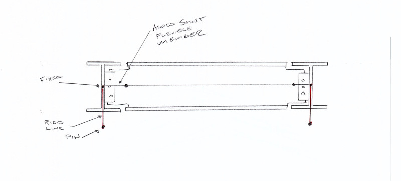
I cant upload the model because of some restrictions by the client. There was definitely a stability issue (it was a mechanism) but I thought it strange that the analysis finished without warnings. My way of getting it to work and still maintain the boundary conditions was to add a short and very flexible beam section at the end of each transverse framing members and and using a fixed connection rather than a pin. After wards I checked that the shear tab connection actually had a moment capacity sufficient to handle the moment in the short little segment at the end of the transverse beams.