bmw318be
Mechanical
- Jun 16, 2010
- 197
Hi,
I have the system of multiple tank that is connected to a common suction and discharge header, the suction header was oversized to accommodate multiple pump running.
1. Common header is 4 inch
2. 4" Tees from common header shall be reduced to match pump nozzle 2" suction and nozzle
I am thinking where should the reducer be installed ideally :
What is the pro and cons for the following scenario
Scenario 1
after Tees
Scenario 2
Before the suction Pulsation Dampener
There a read up for "typical installation straight pipe 10 to 15 pipe diameter to minimize turbulence flow"
Also "metering pump should be sized 1 size larger than pump nozzle to avoid cavitation" . In this case, the pump is 2 inch, if 3 inch used, the reducer shall be installed
The pump is Positive displacement pump, Plunger types.
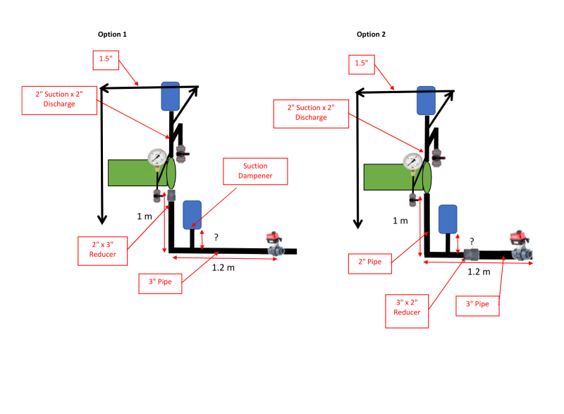
Q1. Where shall i arrange the piping so the reducer has a minimum distance from the pump suction nozzle ?
Q2. If the reducer is installed at scenario 1, would a "vapor trap" is created by the change in diameter as it is vertical lift condition bottom suction 1 m.
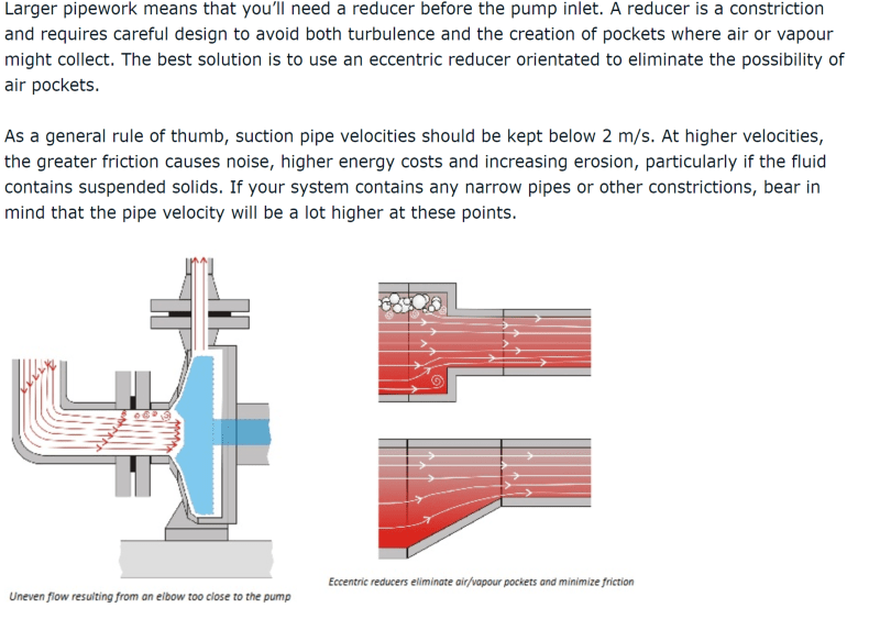
Q3. The concern for reducer, it would collect air pocket which reduce the suction priming of the pump. I attached the reference of horizontal suction that shows the illustration of reducer trapped air. any impact for having reducer of 3 to 2" on the vertical line scenario 1 ?. Or would it be better on the horizontal line ?
I have the system of multiple tank that is connected to a common suction and discharge header, the suction header was oversized to accommodate multiple pump running.
1. Common header is 4 inch
2. 4" Tees from common header shall be reduced to match pump nozzle 2" suction and nozzle
I am thinking where should the reducer be installed ideally :
What is the pro and cons for the following scenario
Scenario 1
after Tees
Scenario 2
Before the suction Pulsation Dampener
There a read up for "typical installation straight pipe 10 to 15 pipe diameter to minimize turbulence flow"
Also "metering pump should be sized 1 size larger than pump nozzle to avoid cavitation" . In this case, the pump is 2 inch, if 3 inch used, the reducer shall be installed
The pump is Positive displacement pump, Plunger types.
Q1. Where shall i arrange the piping so the reducer has a minimum distance from the pump suction nozzle ?
Q2. If the reducer is installed at scenario 1, would a "vapor trap" is created by the change in diameter as it is vertical lift condition bottom suction 1 m.
Q3. The concern for reducer, it would collect air pocket which reduce the suction priming of the pump. I attached the reference of horizontal suction that shows the illustration of reducer trapped air. any impact for having reducer of 3 to 2" on the vertical line scenario 1 ?. Or would it be better on the horizontal line ?