Continue to Site

Eng-Tips is the largest engineering community on the Internet

Intelligent Work Forums for Engineering Professionals

  • Congratulations waross on being selected by the Eng-Tips community for having the most helpful posts in the forums last week. Way to Go!

re-upload of HD retrofit bracket dwg ?

Status
Not open for further replies.

dsilk

Electrical
Aug 25, 2019
2
thread507-420144

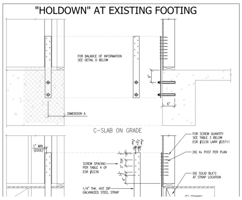
@perland: any chance you can re-post the drawing you uploaded for hold-down bracket alternative to HDs? It seems the original upload cut off the bottom half of the page.

your original post: "Attached is a detail that I use for conditions where HD's with epoxy don't work. The loads used for this detail are uplift x 2.5. Hope this helps."

thanks!
I know it's been a few years:)
Doug
 
Replies continue below

Recommended for you

They haven’t logged on here since January 2018.

Check out Eng-Tips Forum's Policies here:
faq731-376
 
@dsilk,

Maybe someone on Eng-Tips can help fill in the missing details for you. It looks pretty straightforward.

BA
 
@BAretired thanks for the suggestion
I have a remodel going on in CA, my structural Engr spec'd 3 shear sections with 6 underpinnning for hold-down retrofits.
In place is a 'huge' (I think) foundation of 18" wide, 24" deep with 8" x 16" stem wall. Digging down that deep and getting through that concrete cleanly (without hitting rebar) is a huge deterrent.
The option @Perland presented is perfect if it can meet spec. Homeowner not concerned about the visuals of the outside brackets.
However, the missing part of the drawing is the complete drawing for stemwall foundation, and I believe shows the nailing schedule, etc. I was hoping to get the complete dwg to try to convince my engr to spec something like that for this.
Any recommendation?

Thanks,
 
OP said:
...and I believe shows the nailing schedule, etc.

pfft...you wish. Present this to your structural engineer as a concept only and trust them to work out the details and viability. What was shown in perland's original attachment is more than sufficient for that purpose.

OP said:
In place is a 'huge' (I think) foundation of 18" wide, 24" deep with 8" x 16" stem wall.

Huge huh? They teach a lot of shear wall foundation design in your EE program in college? That monster footing probably doesn't do much more than satisfy the bare minimum requirements of the project geotechnical report.

c01_cupro2.jpg


HELP! I'd like your help with a thread that I was forced to move to the business issues section where it will surely be seen by next to nobody that matters to me:
 
I agree with KootK that there is sufficient information in the visible portion of the drawing to understand the concept. The structural engineer on the project must determine how much tension is required at each site location. This would permit him to calculate the size of strap tie, number of screws into the stud and connection to the 8"x16" stem wall.

He would also need to know whether or not the existing vertical reinforcement in the stem wall is sufficient to resist the required tension and that it continues down into the 18" x 24" strip footing. These are details which Eng-Tips members do not know and cannot comment on.

If the strap tie or any hardware extends below grade, it must be adequately protected against corrosion by galvanizing or similar means.

BA
 
Status
Not open for further replies.

Part and Inventory Search

Sponsor