Continue to Site

Eng-Tips is the largest engineering community on the Internet

Intelligent Work Forums for Engineering Professionals

  • Congratulations waross on being selected by the Eng-Tips community for having the most helpful posts in the forums last week. Way to Go!

RC Multicell Box Girder

Status
Not open for further replies.

Shz713

Structural
Aug 21, 2015
221
Good day mates,

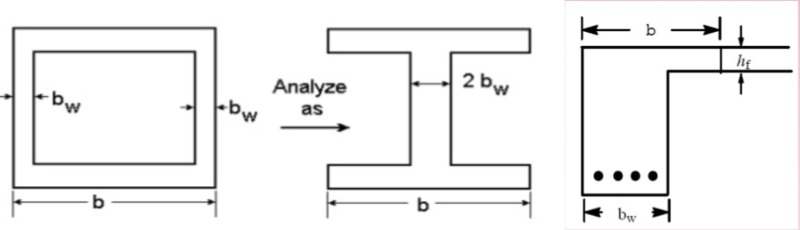
I'm having hard time finding an example design of RC multicell box girder. I need to know how it is designed (whatever design Code does not matter).
I mean interior girders, exterior girders, top and bottom slab how they are designed for max moment and shear resistance?

Thanks ahead engineers
 
Replies continue below

Recommended for you

I'd like to know how such a thing, if it exists, would be manufactured.
Specifically, how do you remove the internal form from the interior cells?


Mike Halloran
Pembroke Pines, FL, USA
 
Well, this RC multicell BGB is built 1971 with cast in-situ footway. Since limited hand drawings are available, I need to manually calculate max design moment. Unluckily, I could not find any example in any bridge design handbook so far, all are PSC/composite bridge.
 
Have you looked at Hambley's Bridge Deck Behaviour? That has examples of grillage analysis for multi-cell box girders, voided slabs, etc.

Doug Jenkins
Interactive Design Services
 
I will give it a try, what I know is that Hambly book is mainly related to grillage analogy.

Structural Health Monitoring/Bridge Engineering

Shoot for the Moon, even if U miss, U still land among Stars!
 
Yet, I appreciate if some experts guide me how to design it. I mean should I consider interior girders as T beam and interior girders as L beam? I do have the longitudinal and transverse demand moment and shear values from software. Now I need to get capacity values in such a way to have adequate capacity/demand ratio. For doing that, I need to know how I must design the RC BGB. Is what shown in picture below appropriate?

download_m3sb2v.jpg


Shoot for the Moon, even if U miss, U still land among Stars!
 
One of the nice things about using a grillage rather than 3D shell models is that it nicely outputs BM's and SF's for the types of sections you chose to represent the grillage with. You're on the right lines yes, make sure you take into account shear lag and the like in checking the structure. Obviously its crucial that the analogy you've used to analyse the bridge is compatible with the way you're designing the structure.

If you do use a grillage, do check whether a modified-grillage might be more appropriate for this type of structure (such as that for steel-composite bridges or precast concrete tub/U girders with an insitu slab). It might be the case that the basic grillage analogy is inadequate for this type of torsionally stiff structure

IIRC Chen's Bridge Engineering handbook includes some guidance on this type of structure as well.

Good luck!
 
Dear UkBridge,

thanks for your insight. As you mentioned, grillage analogy cannot fully model the behaviour of this type of bridge, since they're very stiff in lateral stability (torsion resistance). Grillage model of this bridge exists but the need is now for FEM which I have it already. The main point is I cannot figure out what design criteria (probably AASHO 1970) for this bridge was made. I was thinking to use longitudinal and transverse maximum demand moment and shear using H20-S16 truck loading and get the corresponding resistance capacity.

Shoot for the Moon, even if U miss, U still land among Stars!
 
Status
Not open for further replies.

Part and Inventory Search

Sponsor