Continue to Site

Eng-Tips is the largest engineering community on the Internet

Intelligent Work Forums for Engineering Professionals

  • Congratulations waross on being selected by the Eng-Tips community for having the most helpful posts in the forums last week. Way to Go!

Punching Shear ACI | Calculation Method

Status
Not open for further replies.

bookowski

Structural
Aug 29, 2010
983
Question(s) regarding calculating punching shear capacity per ACI, primarily this is in regards to corner columns:

Is there a clear direction/requirement on how to calculate max stress for corner columns per ACI? I have seen this approached many different ways and have never found a satisfying answer. Looking at 318-11 here but no difference that I know of from previous editions:

- 11.11.7.2 lays out a V/A + M/J procedure for calc'ing max stress. They provide this for an edge condition and state that "similar equations may be developed... for columns located at the corner of a slab". This leaves the accepted procedure at a corner open.

- I have seen many texts and software (SAFE and RAM) which treat corner columns by finding the principal axis and transforming moments to find the M/Jz stress where z is the principal axis.

- I have seen hand calcs that do M/Jx + M/Jy and superimpose the results.

- PCA Notes on 318-11, page 16-15 "where biaxial moment transfer occurs, research has shown that the method for evaluating shear stresses due to moment transfer between slabs and column in R11.11.7.2 is still applicable. There is need to superimpose the shear stresses due to moment transfer in two directions". This is allowing us to check one direction at a time, x and then y.... doesn't seem to be much logic in this other than it possibly has shown to be ok relative to testing.

- From the CSI wiki page for SAFE on "why do results differ from hand calcuations" - "For corner columns, results should differ from ACI and PCA formulation because SAFE incorporates the I23 moment-of-inertia term, leading to more conservative results. We believe this approach to be more theoretically sound." This I23 is the principal axis component mentioned above. SAFE has a white paper where they have verification calcs and show the PCA method vs SAFE.

- Decon, a manufacturer of studrails, has free software - this follows the SAFE approach of finding the principal axis

So I'm seeing 3 general approaches: Check X and Y independently (PCA and maybe ACI?), Superimpose X + Y, Find the principal axis and find M/Iz.

Beyond just being curious this has a very large impact on the results. A corner column in SAFE that has a demand/capacity ratio of 2.0 which would put it beyond even shear reinforcing per ACI. The same condition (same moments, shear, geometry etc) done by X and then Y independently may be well below D/C 1.0 meaning it doesn't need anything. The X + Y approach falls in the middle.

This is a tough sell if I have corner columns that need to be 30x30 for punching shear and the guy down the hall can pull off 16x16.

Am I missing something where this is clarified?
 
Replies continue below

Recommended for you

Nope, it is just that muddy. For new design I will go with the principal axis and both Mux and Muy. It seems the most theoretically sound to me. I can see a reasoning to using only Mux or Muy at a time, equivalent frames in each direction. With the FEM programs nowadays I do not think it is as valid. Shear caps would be a better way to go than huge columns IMHO

Be careful with Decon. They are the folks that more or less developed the studrails and associated theory (in North America anyway). Accordingly they think they are smarter than the average bear so their software includes some things that are not allowed per ACI. One such thing is they will use a greater gamma factors than ACI permits.
 
bookowski said:
Is there a clear direction/requirement on how to calculate max stress for corner columns per ACI?

Not that I'm aware of.

bookowski said:
This is allowing us to check one direction at a time[/b], x and then y....

I interpret this differently. I think that this allows us to calculate stresses, one at a time, about the geometric axes and then superimpose them for a biaxial check. I see no rational basis, nor code support, for checking punching shear about each of the geometrical axes separately and not combining them somehow for a bi-axial check. That being said, I routinely see designers doing exactly that. I think that a lot of folks mistakenly assume that, because moment can be considered independently in the two orthogonal directions, the same holds true for punching shear.

bookowski said:
From the CSI wiki page... we believe this approach to be more theoretically sound."

Like dcarr, I agree with them.

bookowski said:
Beyond just being curious this has a very large impact on the results

Yeah, it's frustrating. Add to this the large variation in practice regarding assumed edge column stiffness etc, and you get a lot of scatter in the results. I know of a big firm that just doesn't model the "columns above" in their slab models. It makes the slab flexural design safer but the punching shear less so as the joint is softened and attracts less moment. When queried, they told me that they just "don't believe" in the amount of moment transfer predicted by the code formulas. How they know this is a mystery to me. Maybe they have an uncle who used to be a multi-story concrete column or something.

I'm fortunate to have easy access to one of the researchers that heavily influenced the code punching shear equations. I won't drop the name because it's been a few years and I may misquote. My recollection is that he told me that it's best to think of punching shear stress as an index rather than a real "stress". Apparently the calculated values really don't reflect anything resembling actual stresses. They're just something to compare to the reported research values. Comforting, I know. If one could find testing for corner columns I would support using whatever "stress" calculation accompanied that testing.


I like to debate structural engineering theory -- a lot. If I challenge you on something, know that I'm doing so because I respect your opinion enough to either change it or adopt it.
 
I would never do x and y independently and not superimpose them - but how do you interpret pca to not allow this. It specifically says "there is no need to superimpose the shear stresses". Seems crazy.

I agree with next level of complexity which is the modeling assumptions, this really muddies the waters. I've seen similar things. I know of one large company here that models all edge and corners as pinned for the same reason you stated, that there isn't sufficient moment transfer. You also have the column above/below assumptions - are they cracked, full height or 1/2 height, fixed or pinned. I know of two other companies here that do the x + y stresses (not principal). In fact as far as I know no one in my area uses straight SAFE results - if they did they couldn't compete. I also know one company that is convinced that the whole thing is a conspiracy by Ghali and Decon to sell studrails.

I can take a column from a D/C of 3.0 to less than 1.0 by varying the assumptions and methods. At that range it seems almost useless, even as a rough index.

Pretty annoying that every few years the codes are updated to address non-issues and something as basic as this is not clarified.
 
If doing equivalent frames or Direct Design it is perfectly logical to look at the punching shear independently in the X and Y directions. Those methods are 2D in each direction independent of the other direction. It makes sense punching shear would be the same. Once you leave those and head into 3D FEM methods I think the PCA statement ceases to be relevant. You need to know what the software is doing before ou decide how to apply that provision
 
Check this out: Link. Frankly, I find it pretty unsatisfying theoretically. However, it seems to confirm dcarr's last comment and the excerpt from the PCA notes.

bookowski said:
I know of one large company here that models all edge and corners as pinned for the same reason you stated, that there isn't sufficient moment transfer.

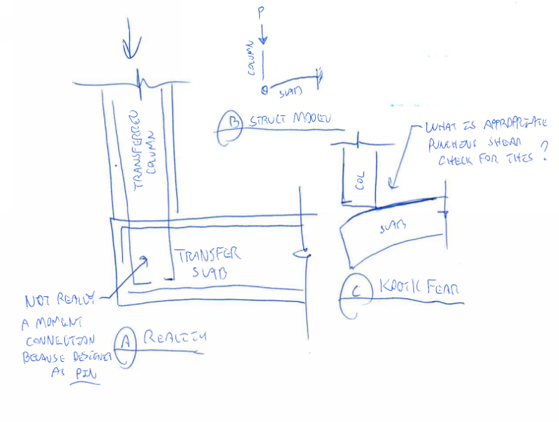
This one really makes my head hurt. My understanding is that punching shear checks are one half of a joint design of which the other half is a proper flexural design (Link). If you essentially disregard the moment transfer altogether, how valid is your shear check? Extreme versions of this happen at roof columns and transferred edge columns on transfer slabs (sketch below). The faux pin assumptions lead designers to check punching shear based on load transferred through the center of the column when, it seems to me, the point of load application would be closer to the interior column edge. Interestingly, this would often move the point of load application closer to the centroid of the critical section. But then the columns would have more applied moment.

We have an extra wrinkle in the Canadian code. We're allowed to do a special, essentially one way, shear check right in front of the column. If that works we can disregard punching shear and punching shear stress moment transfer altogether. I use it often.

Capture_gr3fy4.png


I like to debate structural engineering theory -- a lot. If I challenge you on something, know that I'm doing so because I respect your opinion enough to either change it or adopt it.
 
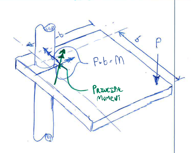
I believe that punching shear should be treated identically regardless of whether FEM or more traditional strip methods (EFM) are used for analysis. In both cases, the moments coming into the columns should be of similar magnitude and acting concurrently (example below). What's good for the goose so to speak. If the paper that I linked to above is to be believed, the reasons for looking at one direction at a time have nothing to do with the analysis method and are, instead, a function of the original development of the equations. Interestingly, the second to last paragraph seems to imply that designers should be mimicking the load cases that underpin the direct design method in order to be consistent with the original development of the punching shear equations. I've never head of anyone doing this.

Capture_g6qcrd.png


I like to debate structural engineering theory -- a lot. If I challenge you on something, know that I'm doing so because I respect your opinion enough to either change it or adopt it.
 
Max stress from principal axes is absolutely correct from a mechanics standpoint, I'm not questioning that. The question is whether or not when checking the max stress against the aci empirical limit this is the method to use (since code methods are not always analytically correct/logical). Seems like it is as ambiguous as I thought, I was hoping that I missed something. ACI must be intentionally not addressing the question.


bookowski said:
Max stress from principal axes is absolutely correct from a mechanics standpoint

I'm not so sure now. I think that it's correct for an un-cracked, elastic material. After reading the CI article, however, I get the impression that it's not so correct for a cracked, plastic material. Punching shear resistance is, as the article states, a planar phenomenon rather than a point stress phenomenon. Two related points of interest:

1) I believe that the punching shear stress equations originated with Timoshenko and, in the original derivation, he did not even mention concrete as the shell material under consideration.

2) I discussed the I23 business with Ghali at a seminar and he claimed that that correlation with test results is actually better when I23 is zeroed out. This seems consistent with the notion of punching shear resistance as planar phenomenon. Over the relatively small vertical surface of a column side, I find it hard to even imagine what an Ixy torsional stress diagonal shear crack would look like.

bookowski said:
The question is whether or not when checking the max stress against the aci empirical limit this is the method to use

As a result of this discussion, and the CI article, I feel fairly confident now that the best approach is to consider independent uniaxial checks only (X and Y independently). This is good news in that I'll be able to dial down the conservatism some, and not just for corner columns. It'll be a little more work than just letting SAFE do its thing of course.

I like to debate structural engineering theory -- a lot. If I challenge you on something, know that I'm doing so because I respect your opinion enough to either change it or adopt it.
 
This is a great discussion about computerized FEA vs slide rule codes, but I found the discussion confusing.

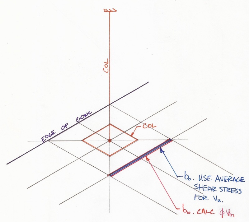
Below is how I've typically modeled this scenario with columns below/above. The case below is a footing where the maximum punching shear stress (P/A +/- My/I) is away from the edge which is typical. It is a moment connection. I don't understand why this would be a pin/hinged connection.

PhotoScan_s9jv28.jpg


For a corner, I don't see why the calculation should be different. Stress transformation, principle axes, and Mohr's Circle shouldn't apply because this is a strength, not stress, calculation.

As a disclaimer, this is just how I've approached the topic. I have no justification for this other that this is how I initially interpreted the codes.
 
There are at least three branches of this discussion:

1. Modeling assumptions: columns above below, cracking of columns, far end column conditions, cracked or uncracked slab etc. I'd leave these aside and assume that whatever methods you use you end up with a Vu, Mux, Muy

2. What is the correct method from a mechanics standpoint to find the max stress for this situation. I need to look into this more before having any confidence.

3. What is the correct method based on ACI to evaluate your max stress and compare it to the code capacity.

#3 is what I'm most interested in because the code method should set the playing field level for everyone.

I just did a rough 2 by x 3 bay model in safe and found the following results:

a. From SAFE (includes Ixy component): A max stress of 444psi giving a D/C = 2.09
b. Worst case of Vu + Mxx or Vu + Myy: Max stress 154 psi giving D/C = .73
c. Vu + Mxx + Myy: Max stress 226 psi giving D/C = 1.07

So the Ixy version versus an X or Y only version is almost a factor of 3. I'm sure that by variation in modeling assumptions you could take that to a factor of 4 or more. Not very satisfying.
 
Some quick thoughts on this based on some work that others in my office did when we worked on RISAFoundation.

1) Like Bookowski said, whatever method you use for modeling / analysis, we start our calculations with a Vu, Mux, Muy. That's not the only way to do it. But, I believe it is the way most easy to understand and most in-line with the code provisions.

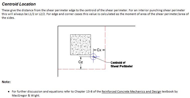
2) When calculating max stress location, it is important to remember that the centroid of the shear perimeter changes when you have a corner case. See below image from our help file.
undefined_hbs09e.png

This has a significant effect on the J value used in the calculation of max tress. The eccentricity between the center of column and centroid of punching perimeter also creates a moment for the calculation even when no moment is applied from the column.

3) We calculate the total stress as the direct shear stress + shear stress due to moment. So, this will always occur at one of the corners of the perimeter. I think this is the intent of the code, though it is not as clear cut with corner columns as it is with edge columns. I tend to look at it as an "unzipping" of the punching shear perimeter. The stress is high enough that the concrete cracks at the max stress location in the punching shear perimeter. Once the crack forms, the resistance decreases and the crack propagates to the lower stress locations.
 
2, in a nice theoretical world I think you find the principal axes at whatever goofy orientation they are when accounting for slab edges and the various sleeves and openings in the slab that are always right near the column. Then you plug and chug to get the stresses.

3. I have seen scenarios where the condition works only when accounting for X or Y moments, and less frequently locations where the condition only works when accounting for BOTH X and Y moments. I go with option b when doing equiv frames, and c when getting moments and such out of FEM type analysis.

 
JoshPlum - thanks for joining in, it will be interesting to hear your interpretation from a software implementation perspective. Calculating J about the centroid and taking the p x e moment into account is correct and I think we all agree on this part of it. In either of the above approaches (principal axes or orthogonal) this would be included.

I see that Risa has an elevated slab program (is this new?) but I don't have access to it. Do you know how Risa handles this? CSI directly addresses this issue in a white paper with a side by side comparison of what they call the 'pca method' versus the principal axes method and states that they find principal axes more theoretically sound. This seems to imply that they interpret the code (ACI) method to be in line with PCA and based on orthogonal axes.
 
I wasn't heavily involved in the testing of our punching shear calculations for elevated slabs. And, I'm not too familiar with that CSI document. Though I pulled up a copy of it (from 2005-ish) and have flipped through it. It's taking me awhile to come up to speed on the "principal axis" concept. Though I believe I understand the basic concept.

Going through our calculations, RISA is using the Vu+Mx+My (option c in your list).

Conceptually, a principal axis approach should work fine. It makes me a little bit uncomfortable as it is not what I've done in the past (with my own hand calcs). But, it might be a better concept from a pure statics point of view. Some things that I would think about from the software development side:

1) This would apply to unsymmetric edge punching as well as corner punching.
2) We'd have to make sure that the two solutions converge. Meaning that an edge perimeter that is ever so slightly asymmetric would produce the same result as one that is perfectly symmetric.
3) Similarly, we'd have to make sure that an edge condition that is extremely asymmetric (where it approaches the corner solution) produces the same behavior (stress wise) as the corner condition.
4) Do the code provisions easily allow this alternate form of analysis (especially if it is more liberal)? Or, are we going out on a limb?
5) Do users truly want this (especially if it is more conservative)? If the group is very much split, then would we have to provide a Global / Project preference to do it either way.
6) How do you present the results to the user in a way that is easy to understand?

Number 6 is actually really important, plus it is a lot more difficult than it sounds. If the user doesn't understand the results the program is showing, and can't reproduce them then they won't trust them. And, any additional program accuracy is wasted because the user doesn't believe it and runs their own side calc.


Note:
I want to say that we had the principal axis method at some point in the past, then pulled it out. I remember having a conversation with someone about the source code and where did our Jxy value came from. But, that would be 6+ years ago and my memory about this is pretty vague and I cannot be sure

I am sure, however, that we went through some verification problems (based on the PCA method) couldn't match the program's more conservative numbers. I believe we went deeper into the issue based on item #2 or #3 in my previous post. Where we created two nearly identical cases that produced very different results. That unequivocally indicates a flaw in the program logic. And, we corrected the flaw.... Probably by stripping out the principal axis stuff completely.

Now, it's possible that the concept is fine and that the developers implementation had a bug that does not exist in the CSI implementation. But, it does strike me as odd / wrong-ish that the two approaches should result in such different results.
 
@JoshPlum - Thanks, this is an interesting twist. I assumed that most software would take the principal axis route since it produces by far the most conservative values, even though it's not clear that is what the code wants you to do.

If you read up a few posts you can see an example that I ran comparing the max stress from the different approaches. I have checked this many times and there is always a very large variation. My current method is the Vu + Mx + My approach (same as risa) done via a personal spreadhseet that takes forces from safe. So on all of my safe models I see the safe values and then I see my v + mx + my values and it is very common to get a D/C > 2.0 in safe and then by spreadsheet be perfectly fine (<1.0).


We were simulposting there - I agree that it does not sit well that the two approaches have such different results yet both seem to be integrated into practice.

I think Ram Concept does principal axes but now I'm not positive, I'll double check.
 
I'm probably beating a dead horse at this point. But, when my brain gets locked onto a subject I sometimes have trouble putting it aside.

Anyway, the more time I spend on this subject, the more my memory of our past issue is improving. I'm now thinking it wasn't a comparison of two nearly identical cases that caused us to label our method incorrect. Though that is a perfectly valid test and we may have done that as well.

Instead, I'm remembering cases where the program was investigating punching shear that should have clearly been an edge or interior failure and was mis-diagnosing it as a corner failure. You see, RISA checks all three types of potential failure perimeters and then determines which one controls. And, we had cases where the corner punching calculations were controlling in cases where anyone could look at them and intuitively know that a corner failure wasn't realistic.
 
bookowski said:
#3 is what I'm most interested in because the code method should set the playing field level for everyone.

ACI 352.1R-11 Guide for Design of Slab-Column Connections in Monolithic Concrete Structures said:
Effects of simultaneous bidirectional moment transfer should be considered in design of the the connection...

It's not exactly the 11th commandment but it's all that I could come up with for official ACI dogma. Does independent uni-axial evaluation based on suitably calibrated shear capacity estimates qualify as consideration of simultaneous bidirectional moment transfer? Last Thursday I would have said no. PCA and the article that I linked to say yes. Now I say... maybe?

ACI 352.1R-11 Guide for Design of Slab-Column Connections in Monolithic Concrete Structures said:
RC corner connections...may be assumed to have adequate shear strength if the factored direct shear transferred to the column does not exceed ...0.5 x phi x Vc

This is the analog to that CSA provision that I mentioned above and may well be the way to go. It's sure a lot easier to apply, that's for certain.

I like to debate structural engineering theory -- a lot. If I challenge you on something, know that I'm doing so because I respect your opinion enough to either change it or adopt it.
 
Status
Not open for further replies.

Part and Inventory Search

Sponsor