Tek-Tips is the largest IT community on the Internet today!

Members share and learn making Tek-Tips Forums the best source of peer-reviewed technical information on the Internet!

  • Congratulations MintJulep on being selected by the Eng-Tips community for having the most helpful posts in the forums last week. Way to Go!

Pumps with VFDs

sdbarry

Mechanical
Joined
Dec 26, 2012
Messages
1
Location
GB
Dear Fellow Members

This is Sulaiman Dawood working as a Project Engineer in Energy Futures Consulting.

I am doing a project for a client and I am stuck at pump analysis with VFDs.

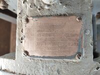
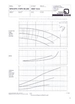
The nameplate of a pump is attached along with the pump curve.

Can you please guide which curve to use with the nameplate's parameters? Also, how will the pump input power change if we reduce the rpm, given that BHP is 18.8kW on the nameplate?

Looking forward to your guidance.

Best Regards

Sulaiman
 

Attachments

  • WhatsApp Image 2025-04-18 at 8.53.38 PM (1).jpeg
    WhatsApp Image 2025-04-18 at 8.53.38 PM (1).jpeg
    281.5 KB · Views: 7
  • Pump curve.jpg
    Pump curve.jpg
    288.7 KB · Views: 7
Last edited:
Do you really know virtually nothing about pumps?

First get the KSB chart for nominal 3000 or 2950 rpm.

Then to find the impeller diameter of pump find out where on the 3000 rpm chart, a duty point of 500 US GPM and 125 ft heat sits. That becomes your curce which is in parallel with the min and max diam curves.

Then for a VFD the performence of any ooj t on the curve changes more or less in proportion to the affinity laws.

Flow is proportional to the relative speed compared to 3000 rpm. So say 3750 rpm or 25% more than 3000 will give you 25% more flow. 2250 rpm 25% less
Head is proportional to rel speed ^2. So 25% more speed is 56% more head, equally 25% less is 56% less head
Power is proportional to rel speed ^3. I think you get the drift now??

But you can't exceed the power of the motor without it going up in smoke.

Does that make sense?
 

Part and Inventory Search

Sponsor

Back
Top