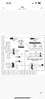
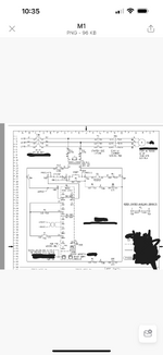
The schematic above has to be automated. What would be the best two options to put a START relay in the Bucket for pump remote start .Mind you, this pump already has a low level cut off so what’s needed is just to start it remotely. The idea is to put a start relay and wire it to a DCS DO Charm and configure it to start based on Level
Navigation
Install the app
How to install the app on iOS
Follow along with the video below to see how to install our site as a web app on your home screen.
Note: This feature may not be available in some browsers.
More options
Style variation
-
Congratulations MintJulep on being selected by the Eng-Tips community for having the most helpful posts in the forums last week. Way to Go!
You are using an out of date browser. It may not display this or other websites correctly.
You should upgrade or use an alternative browser.
You should upgrade or use an alternative browser.
Pump Remote Start 1
- Thread starter EEENGRX
- Start date
- Moderator
- #2
From an industrial control background:
I would use a level control relay and wire it according to the instructions that come with it.
I would use DCS to monitor and report.
If DCS control was desired, I would leave the primary control with the level relay and use DCS NO and NC contacts in parallel or series with the level control rely contacts.
In the level range between start level and stop level, the pump may either be running or stopped depending on the recent operating history.
From a computer control background:
Probably less than optimum.
I have seen a couple of disasters when DCS first control had precedence over relay first control.
The "DCS" first control philosophy by computer nerds who didn't understand motor control had the real potential to snap the shafts of large motors.
This was on a very large pulp and paper complex.
- Thread starter
- #3
Great insight. What about putting an interposing Relay in the START circuit . The primary function will be to close the circuit and start the pump and have the NO contacts wired to the DCS DO contacts and configure it to start/ stop pump based on Level with an already existing Level Transmitter. Let me know your thoughts
- Moderator
- #4
Are you familiar wit the basic three wire motor control circuit?
Start with a basic three wire motor control circuit.
Add low level contacts in series with the stop button.
Add high level contacts in series with the start button.
If the level signals must come from the DCS, functionally the DCS contacts may be used directly or you may use an interposing relay(s).
Caveats;
1. You may wish to avoid short stopping.
If the current to a running motor is interrupted for a short time and then re-energized, there may be violent transients developed, both electrical and mechanical.
The electrical transient may exceed locked rotor current. The mechanical transient may break motor shafts or damage driven equipment or break couplings.
The danger zone is generally less than 8 seconds and is the worst in the first second or less.
The danger time is when the upper limit has closed but the liquid level has not dropped enough to open the high level contacts.
This may be avoided by interposing a timing relay.
Would you like to humour me as I revisit a distant past?
Many years ago I taught motor control circuits to classes of journeymen electricians.
We had actual motor control equipment and small motors so that the students could wire up their circuits and prove them out.
The students started by wiring up each typical control scheme for a single motor.
They were supplied with a booklet of wiring diagrams.
Once they completed the single motor assignments they started working on multiple motor control schemes.
For this part of the course, no diagrams were supplied.
The students were given a description of the intended operation and the students developed their own diagrams.
I did not give instructions but did ask leading questions.
See if you can download the diagram and then edit it.
You start by making additions and posting them.

- Moderator
- #5
First assignment:
Some information for me.
What type of level control do you have.
Does it have contacts that operate at the appropriate levels?
Can these contacts be used directly or must the signals be passed through the DCS?
2nd assignment. Edit the digram to insert a set of low level contacts in the proper place.
- Thread starter
- #6
LOL..I completely understand your point and I do have the history of the actual running conditions. This motor was designed with no remote start, just a low Level cut off. I am considering ways to add a remote start to the schematic. I looked at ways to program this via DCS but it hasn’t worked quite well and I’m still looking into that option via Modbus .hence the option of using an interposing relay to start it based on Level and the existing low level stop will complement it.I am looking at wiring the Relay across the Start bottom and in Parallel , that way I can use the physical start bottom and DCS remote start as well. I have a Radar LT and Pump is started in the field but will trip at a certain Low Level. Trying to go with the best option for remote start. Do you
- Moderator
- #7
I don't think that you will be happy with a maintained contact in the start circuit.
You should lose your DCS signal to the motor starter as soon as the DCS loses the signal from the high level switch.
If you use an interposing relay I suggest a timing relay for Rapid-restart protection.
This is not a must.
I have many times done level control without that added protection.
You should lose your DCS signal to the motor starter as soon as the DCS loses the signal from the high level switch.
If you use an interposing relay I suggest a timing relay for Rapid-restart protection.
This is not a must.
I have many times done level control without that added protection.
- Thread starter
- #8
-
1
- Moderator
- #9
A scheme to avoid:
The high level sets the DCS output and the pump runs.
The low level re-sets the DCS and the pump stops.
The local stop button stops the pump for as long as the button is pushed but does not re-set the DCS.
When the stop button is released, the DCS re-starts the pump immediately.
This may lead to unintended consequences.
Similar threads
- Question
- Replies
- 1
- Views
- 1K
- Replies
- 42
- Views
- 11K
- Question
- Replies
- 10
- Views
- 11K
- Locked
- Question
- Replies
- 5
- Views
- 428
- Locked
- Question
- Replies
- 2
- Views
- 490


