Good Morning,
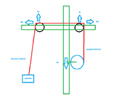
I hope everybody is well. I’m currently working on a mast design (green structure) that incorporates two pulleys (black) and one winch (blue) & wire rope (red). Based on my rough analysis, the structural steel frame (green) is expected to experience the following reaction forces:
Ra, Rb, Rc, and Rd at the pulley bearing points
Re at the bolted interface between the winch and the steel structure
Questions:
- Does my FBD makes sense or am I missing something?
- Are there any tools / spreadsheets / programs to solve those problems ?


