MJC6125
Structural
- Apr 9, 2017
- 120
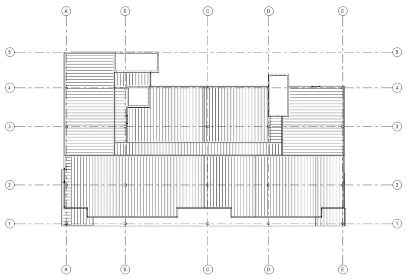
I have a few questions for how you apply loads to a PT podium slab from the load bearing walls that sit on the slab. I have Adapt PT that I can use for design, so these questions would be specific to using the equivalent frame method of analysis. See plan below for reference, which has boxed numbering that corresponds to the question numbering below (where applicable).
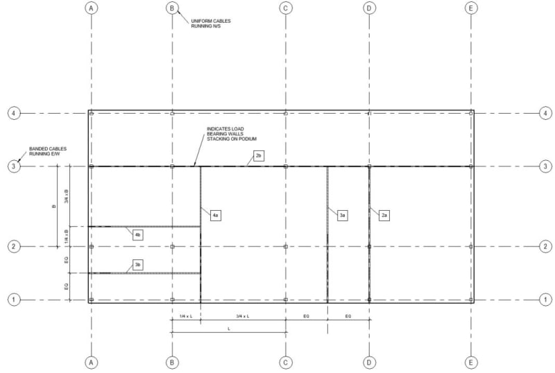
1. When you check the slab design are you always using strips that run along the column lines and are sized based on how far it is to adjacent column lines? Or do you ever check the uniform cables on a plf basis or a strip size that you choose based on loading (i.e. a 4' strip that has a load bearing wall running parallel and over the top of it)? This second option would be analogous to a one way slab with your banded tendons acting as a beam that supports the one-way slab and its loads.
2a. If you have a load bearing wall running directly on top of a column line in the uniform direction, does that load need to be applied to the slab design in the banded direction? (maybe it wouldn't matter if it was because the load will go directly into the support and won't affect the slab bending?)
2b. Same as 2a, but with the wall in the banded direction?
3a. If you have a load bearing wall running parallel to the uniform direction but at the midspan between two column lines, Do you put half of that load into each adjacent column line?
3b. Same as 3a, but with the wall in the banded direction?
4a. If you have a load bearing wall running parallel to the uniform direction but at some random point between two column lines (i.e. a 1/4 point), Do you put of portion of that load into each adjacent column line based on a ratio of how close it is to each column line?
4b. Same as 4a, but with the wall in the banded direction?
5. Do point loads work the same way as linear loads in terms of how it is incorporated into the design of different strips?