Tek-Tips is the largest IT community on the Internet today!

Members share and learn making Tek-Tips Forums the best source of peer-reviewed technical information on the Internet!

  • Congratulations LittleInch on being selected by the Eng-Tips community for having the most helpful posts in the forums last week. Way to Go!

(Pressure) design of welded-in branch connection per B31.3 304.3.3

Status
Not open for further replies.

XL83NL

Mechanical
Joined
Mar 3, 2011
Messages
3,121
Location
NL
We've bought some orbital weld fittings for which I would like to calculate the allowable pressure per B31.3 using para 304.3.3, as the MFR lacks in doing so and I want to know if the fittings can be used for our application.

Area A4 of fig 304.3.3 is (obviously) not present, but due to the design of the fitting Im having trouble to calculate the other applicable 'pressure areas' per this section;
- I believe A1 is not present due to the weld-in design
- Can I assume A2 and A3 to be present?

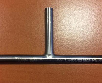
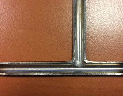
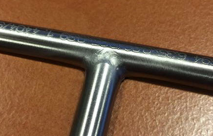
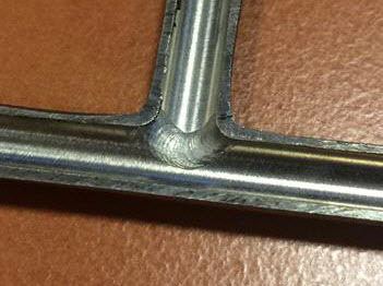
The fitting under consideration is made of two A269/213 316(L) tubes, 1/4" x 0.035", (machine/auto) welded together as per below pictures:
IMG_2657_Small_szbtno.jpg
IMG_2658_Small_hknhce.jpg


IMG_2660_Small_kzxech.jpg
IMG_2659_Small_izj2s4.jpg


As per 304.3.1(b)(1) I dont see as of now that this design is not allowed, but figure 304.3.3 makes this design quite tricky for calculation. Or am I missing something?
 
XL83NL,

The branch reinforcement calc in 31.3 is an area replacement model. In other words the area of the pipe you've removed from the header needs to be replaced by other metal, within a set distance from the OD or the CL of the branch.

What 31.3 allows you to do is to use the thickness you need for pressure (th and tb) as the area you need to replace, but if your pipe has extra thickness due to it being thicker than the minimum for pressure, then this can count towards your area replacement. E.g. you only need 2mm for pressure, but your pipe is 3mm thick then you have the 1mm area available for "reinforcement". Which is A2 and A3 ( corrosion allowance and manufacturing tolerance need to be removed first). You can't assume it - you need to calculate it.

I think you have some area A4, as the picture looks thicker in the cutaway section. You should measure this extra thickness at the crotch compared to the nominal thickness of the branch and header and use it - I think you're going to need it.

you could always use a fabricated tee....


Remember - More details = better answers
Also: If you get a response it's polite to respond to it.
 
Hi LI, thanks for your reply. I understand I need to calculate it, which is why I started this post. I am not sure you have understood my issue completely, so Ill try to be more exact.

My 'assumption' was wrt fig 304.3.3. Due to the design of the tee, Im not sure if the excess thickness (which is there) can be used for calculation of areas A2 and A3, as fig 304.3.3 depicts a different design. The note under 304.3.3 says the figure illustrates the nomenclature, and does not indicate complete welding details or a preferred method of construction. In fact, fig 328.5.4D(2) illustrates my design to some extent, but Im hesitant to believe it's the same. Furthermore, I believe area A1 is not present in my design.

In other, can I assume this design meets (figure) 304.3.3 wrt areas A1, A2 and A3, assuming A4 is not present (sure there's a crotch, but Ill keep that as a last resort as it's sooo tiny).

PS: fabricated tees are an option, but for this appliciation, way more expensive.
 
Agreed it's a bit different so you might be good to look at fig 304.3.4 which is more like your actual shape..

For me A2 and A3 are quite clear and they are simply the "excess" material left by subtracting the min thickness needed for pressure plus the manufacturing tolerance and any Corrosion allowance from the actual nominal thickness of header and branch.

A4 is the weld material which is what your excess is, but for a curved tee connection maybe 304.4.3 is better.

Of course A1 is present - this is the material removed from header pipe to allow fluids to pass to and fro! Check appendix H for sample calculations and the criteria for whether you need more re-inforcement is whether (A2+ A3+ A4) > A1. So A1 is the first thing you calcualte

But yes I believe 304.3.3 matches your photos

Remember - More details = better answers
Also: If you get a response it's polite to respond to it.
 
Thanks. Ive did some calcs and yes, d1 is there 'fo sho'. Fig 304.3.4 does not match my design, as the branch-intersection is not initiated with an extruded profile. Theyve simply drilled a hole in the run 'pipe' (and did no further extrusion on the hole in the run). If you look closely at the photo's you can see the weld profile which ends in the pipe, not 'above'. After finishing the calcs I dont need area A4 @ 200 °C w/ 200 bar(g), using c = 0 mm., but it's on the edge.

App. H is a good one, unfortuantely no exmaple matches my case though.
 
Status
Not open for further replies.

Part and Inventory Search

Sponsor

Back
Top