Tek-Tips is the largest IT community on the Internet today!

Members share and learn making Tek-Tips Forums the best source of peer-reviewed technical information on the Internet!

  • Congratulations MintJulep on being selected by the Eng-Tips community for having the most helpful posts in the forums last week. Way to Go!

PRD Reaction Forces 4

Status
Not open for further replies.

dozer

Structural
Joined
Apr 9, 2001
Messages
509
Location
US
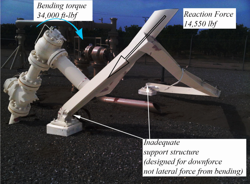
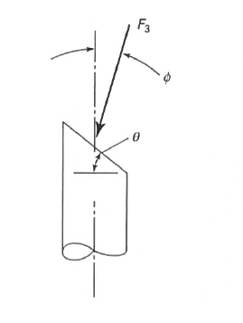
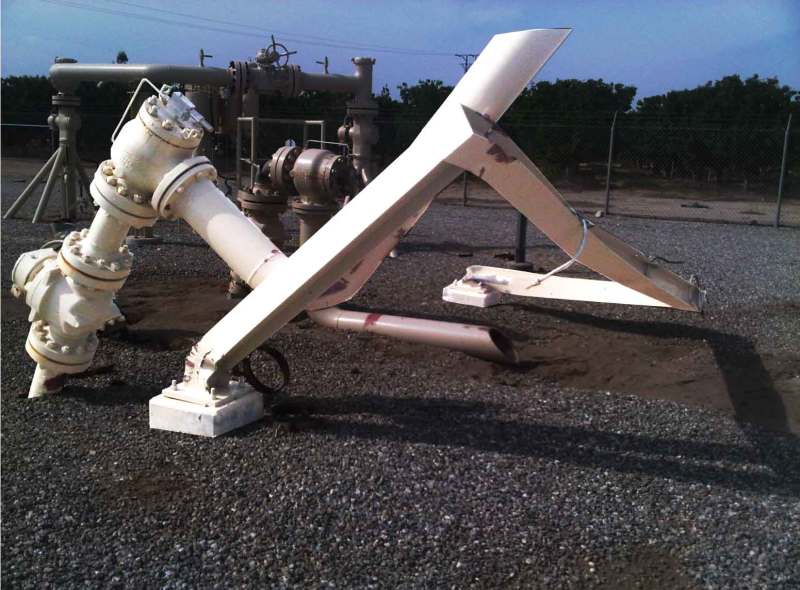
API 520 gives an equation to determine the force at the point of discharge of a pressure-relieving device (PRD). I understand that but intuitively it seems like there would be something going on at the valve itself. I've attached a drawing of a segment of piping that includes 4 PRD's for reference. So when deciding how to support this you would obviously consider it's weight and the reaction force at the outlet. To keep it simple let's not consider temperature changes, wind, or seismic. Would you throw in some inertial force (or fluid flow or whatever) at the valves themselves or anywhere else? If so, how would you calculate? A reference explaining it would be great if it's too involved to describe here. I'm familiar with the concept of a control volume in fluid mechanics and it seems like that may contain the answer but I'm not sure I have enough data or a big enough brain to apply it.

Oh, and I'm sure many of you are going to have reasons why this is not a very good layout. That's fine, feel free to expound. We've actually got someone marking up the drawing as I type this but my fundamental question remains the same.
 
 http://files.engineering.com/getfile.aspx?folder=0e445c41-2f4f-479d-9149-788a3cdf39cd&file=PSV_System.pdf
Ch05Fig10_oupocv.jpg


[bold]David Simpson, PE[/bold]
MuleShoe Engineering

In questions of science, the authority of a thousand is not worth the humble reasoning of a single individual. Galileo Galilei, Italian Physicist
 
David, actually they exacerbated the problem by cutting the slant the wrong way on the exhaust pipe. If they would have cut it opposite of how it is the reaction force would have been more in line with the valve thus reducing the moment. Who knows, maybe it would have been enough to save the pipe and support. Maybe not.
Reaction_clrubn.png

Anyway, I'm hijacking my own thread. I get that there is a reaction force at the tip of the exhaust. If you look at the model I attached, you will see that the PRD's are a long way from the exhaust. Technically, API 520 says the equation is for one elbow and a vertical exhaust pipe, so maybe I'm already in no-man's land. What I'm wondering is, if you have a support (or two) near a pressure relief valve and you have adequately supported the exhaust pipe which is quite a bit further away. Does that support (one near the PRV) feel any extra load when the valve opens?

Like I said, intuitively it seems like it would but I can't find anything that talks about that. Hoping some experts here can give me a sense of what is going on.
 
zdas04, can you repost that picture but without added text? It's a great picture we can use for our company internal relief valve course, as an example of incorrect supporting installation.
 
I'm just curious, XL83NL, are you referring to the slant being incorrect or is there something else you see?
 
Not sure if the slant is incorrect - I was interested only in the picture because of the strutcutral steel that was torn. But if there are more things incorrect, Id like to hear (Im not PSV expert by any means so keep me informed)
 
Ch05Fig10NoText_y1xlvj.jpg


[bold]David Simpson, PE[/bold]
MuleShoe Engineering

In questions of science, the authority of a thousand is not worth the humble reasoning of a single individual. Galileo Galilei, Italian Physicist
 
dozer,
I've spent the morning looking at videos of gathering system blow downs (I have several that I took myself and found more on YouTube). If the slant of the cut mattered, then the blowdown plume would be skewed from the pipeline centerline. I can't find a single case where the plume was any different with or without a bevel on the end of the pipe. The area of the opening (normal to the cut surface) is larger than the pipe cross sectional area by the square root of 2 if the angle is 45°, but the plume doesn't seem to be modified from the pipe diameter and centerline until several pipe diameters past the end of the pipe. If the force were normal to the cut face, then you would see an offset to the pipe centerline and you never do.

One of the secondary (maybe tertiary) forces in this scenario is friction, and there is no friction where there is no pipe, but I don't believe that the friction on the pointy side of the pipe is enough to skew the force profile to be normal to the cut face, or really to skew it in any measurable way. The dP due to friction in the entire tail pipe is a fraction of a psi.

If I still had wells to play with I'd set this experiment up and measure the lateral force, but those days are far in my past (14 years on September 1). I'm betting that just connecting a fish scale between the pipe and a support strut and opening a ball valve would show that the lateral force is the same regardless of the slope angle of the bevel.

[bold]David Simpson, PE[/bold]
MuleShoe Engineering

In questions of science, the authority of a thousand is not worth the humble reasoning of a single individual. Galileo Galilei, Italian Physicist
 
There is a force on the valves due to the high velocity flow, but in your case it is matched by the near identical force on the attached elbow pointing down. So long as the flange & pipe between the valve and the elbow is strong enough then these forces cancel out. If the valve was simply venting horizontally then you would have a considerable force acting horizontally on the valve.

The issue comes at the end point of the vent where there is no balancing force other than that supplied by the support.

In the photo I'm working on the basis that the support was only attached by a U bolt to the vertical leg of the vent and has sheared off and also been pushed over. If the beam was instead under the horizontal bit then it should have taken the load.

The brown valve just beyond the white one has sheared off completely! and by the look of it was also U bolted to the beam.

your pipe isometric view doesn't show any supports, but so long as your long horizontal bit is supported properly then there should be relatively low forces or movements.

I'm with Dave on the angle of the vent. I can't see any reason to modify the force angle. If you had put a 12.5 degree elbow then that's different, but not a cut angle like that.

Remember - More details = better answers
Also: If you get a response it's polite to respond to it.
 
LittleInch,
If you zoom in on the brown valve, it looks like it was either unsupported or the support was removed early in the process (by the other valve bending it away maybe?) and the spool piece between the PSV and the block valve is bent 90°. It is still connected.

[bold]David Simpson, PE[/bold]
MuleShoe Engineering

In questions of science, the authority of a thousand is not worth the humble reasoning of a single individual. Galileo Galilei, Italian Physicist
 
ok, that was some ductile piece of pipe!

The support when you zoom in seems to have two dents / U bolts which match up to the location of the vents. So support seems to be incorrect as they were just supporting it int he vertical plane instead of under the pipe.

I've seen another one like this supplied by BI, but can't find it where the spool up to the valve had been sheared off by the reaction force. (might have been the same place or the same designer....)

Remember - More details = better answers
Also: If you get a response it's polite to respond to it.
 
I think that it was the brown relief valve that vented. The U-bolt clamp slipped and the vent pipe moved down causing rotation around the point where the pipe leaves the ground to connect to the relief valve. This rotation pushed over the pipe support beam. You can see the ground is scoured at the exit of the brown vent pipe.
 
Having a picture (or iso) of the original situation for the photo shown above would really help. I have a hard time understanding what happened, and what caused it.
 
XL83NL,
Sorry, you are on your own for that one. I found the picture in a government publication on the accident report, but I don't have a link back to the report anymore.

[bold]David Simpson, PE[/bold]
MuleShoe Engineering

In questions of science, the authority of a thousand is not worth the humble reasoning of a single individual. Galileo Galilei, Italian Physicist
 
Well, I guess this thread has been officially hijacked. At least it's an interesting hijack. Thanks Littleinch for your reply.
 
Not certain I believe a spool piece like that could be bent 90 degrees and not fail.

Any chance they replaced it with an elbow immediately after the initial incident to keep the system live while a real solution was engineered?

Agree that the scoured ground indicates the brown valve has been venting with the outlet in it's photographed position.
 
I agree, XL83NL, something(s) looks off in the photo.
 
jgKRI,
The engineer that would purposely put their PSV outflow in a location that guaranteed that rocks, gravel, and dirt would have to become projectiles is not an engineer that I would ever want to work around. I don't believe that that pipe started in that orientation.

[bold]David Simpson, PE[/bold]
MuleShoe Engineering

In questions of science, the authority of a thousand is not worth the humble reasoning of a single individual. Galileo Galilei, Italian Physicist
 
I remember looking at that incident when it first came out on CCPS (or wherever). That elbow was bent in the incident. It probably happened in a fraction of a second. Like David, I can't find it now though. Yep, the supports should have been UNDER the horizontal (initially) PSV outlet pipes.

Good luck,
Latexman

To a ChE, the glass is always full - 1/2 air and 1/2 water.
 
The orientation of the support columns also contributed to failure. If rotated 90 degrees the column flanges would be oriented to be stronger in bending.
 
Status
Not open for further replies.

Part and Inventory Search

Sponsor

Back
Top