Tek-Tips is the largest IT community on the Internet today!

Members share and learn making Tek-Tips Forums the best source of peer-reviewed technical information on the Internet!

  • Congratulations MintJulep on being selected by the Eng-Tips community for having the most helpful posts in the forums last week. Way to Go!

PRD Reaction Forces 4

Status
Not open for further replies.

dozer

Structural
Joined
Apr 9, 2001
Messages
509
Location
US
API 520 gives an equation to determine the force at the point of discharge of a pressure-relieving device (PRD). I understand that but intuitively it seems like there would be something going on at the valve itself. I've attached a drawing of a segment of piping that includes 4 PRD's for reference. So when deciding how to support this you would obviously consider it's weight and the reaction force at the outlet. To keep it simple let's not consider temperature changes, wind, or seismic. Would you throw in some inertial force (or fluid flow or whatever) at the valves themselves or anywhere else? If so, how would you calculate? A reference explaining it would be great if it's too involved to describe here. I'm familiar with the concept of a control volume in fluid mechanics and it seems like that may contain the answer but I'm not sure I have enough data or a big enough brain to apply it.

Oh, and I'm sure many of you are going to have reasons why this is not a very good layout. That's fine, feel free to expound. We've actually got someone marking up the drawing as I type this but my fundamental question remains the same.
 
 http://files.engineering.com/getfile.aspx?folder=0e445c41-2f4f-479d-9149-788a3cdf39cd&file=PSV_System.pdf
My recollection is there is a full report/presentation out there. I saw it at one time. I don't think I have it now. I suspect it can be found if someone really wants it. And, yes, column rotation was a finding.

Good luck,
Latexman

To a ChE, the glass is always full - 1/2 air and 1/2 water.
 
Ok, ok. I'm interested in this topic as well as topicstarter is and I would like to find a gist. Picture is really great. It is so cute that I'm ready to print and sleep hugging it. But topic has not been answered. Is or is not there any force that shall be taken into consideration in bends, relief valves etc?

I have encountered PSVs in high pressure polyethylene plant that had set pressure >2kbarg. Contractor provided for Operator a calculation record and stated that during relief forces in bends rise:
- in PSVs up to 5.8kN
- in bends downstream of PSVs up to 8.8kN
Links to some extractions - one, two. I'm not sure this calculation should be believed, but anyway. There is a real problem as a min I have encountered. Operator was anxious about this case and demanded from Contractor an evidence because in the past Operator had an accident with PSV in steam service - during relief downstream pipe was torn away and injured a worker. Contractor provided a calculation record that forces inside (not exhaust) pipes were calculated and taken into account.

Can anybody provide a clear statement and a proof? If forces shall or should be taken into account than can links be provided to documents to calculate forces inside pipes?
 
zdas said:
The engineer that would purposely put their PSV outflow in a location that guaranteed that rocks, gravel, and dirt would have to become projectiles is not an engineer that I would ever want to work around. I don't believe that that pipe started in that orientation.

But you believe that:

A) that spool piece could bend (what appears to be) exactly 90 degrees, with a very tight bend radius and no support and not fail

AND

B) that spool piece could be bent exactly 90 degrees without (what appears to be) any significant deflection of the rest of the stack

Seems pretty unlikely to me.

I agree that the outflow causing a spray of debris absolutely would happen in this configuration.. but if the engineer's choice was between creating a projectile stream and not being able to operate the plant or system this is attached too, maybe his hand was forced. I don't envy his position.
 
Shvet, thanks for trying to get this thread back on topic. The drawing you linked to with the internal forces is exactly what I'm asking about. That being an isometric drawing without any x, y, z force components listed makes it hard to tell which way some of the arrows are pointing although you can figure it out using common sense. Notice a lot of them nearly balance which is what LittleInch is saying. I do see some that don't seem to have an equal (or roughly equal) and opposite reaction. If that is correct then that is somewhat disconcerting to me because I don't know that I've ever seen that taken into account.

I know that the PSV failure is thrilling but if anyone has a reference for computing these forces that would be great.
 
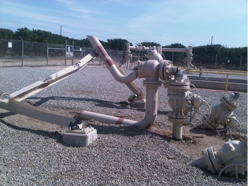
I found the full report, which contains better pictures.


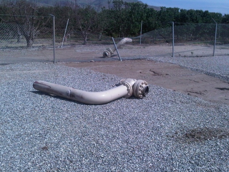
The reverse shot shows quite clearly that the spool piece failed not just on the second stack, but on two more that are difficult to see in the first photo. Second two failures threw the valves and their vents clear.

1_llus7g.jpg


2_d3ielj.jpg
 
Spot on jgKRI! Upon further review of the original routing for situation of the photo's shown, there are some similarities between that and what the OP is posting; 4 reliev valves. However there are also differences involved, and I think you carefully all the possible scenario's of relief. And what it does to the system. Also, you have led all relief lines into 1 vent. Do a dynamic analysis and as kthe PRV vendor for input of the relief loads.
 
jgKRI,
I'm not sure why you got in my face over this. The picture that you posted demonstrates that no one designed that PSV to blow along the ground, that is where it ended up after it failed. You should have done your research before you got mouthy.

[bold]David Simpson, PE[/bold]
MuleShoe Engineering

In questions of science, the authority of a thousand is not worth the humble reasoning of a single individual. Galileo Galilei, Italian Physicist
 
You apparently didn't read my first post.

The question which I asked was whether or not it was possible that if that assembly was straight, the straight spool piece was replaced with an elbow to lay the vent on the ground so that the system could be operated while a repair or replacement to the supports was engineered.

I never thought, or implied, that the original design intent was that the vent would be anywhere near the ground.

I then did my research by finding the full report, which took about 20 seconds.

I wasn't "in your face".

I was having what I thought was a civil difference of opinion. If you took that as aggressive, maybe you need to dial back the sensitivity a little.
 
jgKRI,
{Quote (zdas)}
The engineer that would purposely put their PSV outflow in a location that guaranteed that rocks, gravel, and dirt would have to become projectiles is not an engineer that I would ever want to work around. I don't believe that that pipe started in that orientation.{/quote}

But you believe that:

A) that spool piece could bend (what appears to be) exactly 90 degrees, with a very tight bend radius and no support and not fail

AND

B) that spool piece could be bent exactly 90 degrees without (what appears to be) any significant deflection of the rest of the stack

Seems pretty unlikely to me.

Still seems pretty judgmental to me. Just for your future reference saying "but you believe that ..." and "... seems pretty unlikely to me" will always come across as attacking and many people here will red flag that sequence out of hand. My "sensitivity" is dialed in pretty well. I'm here because I want to be, but that desire diminishes every time someone ascribes beliefs to me that I don't hold.

[bold]David Simpson, PE[/bold]
MuleShoe Engineering

In questions of science, the authority of a thousand is not worth the humble reasoning of a single individual. Galileo Galilei, Italian Physicist
 
I asked a question, with the hope that someone who knows these systems better than I do would respond and I'd learn something.

My desire to work with an engineer who calls someone 'mouthy' for asking a question and then spending their own time searching for the answer when one isn't given, is approximately equal to your desire to work with an engineer who would put a PRD vent near and parallel to the ground.

I don't know how you've survived as an engineer if you interpret a request for information, a difference of opinion, or a request for clarification of an opinion as aggressive. Do yourself, and anyone who might dare ask a question, a favor and keep your condescension to yourself.


Getting back on topic:

Any reason why the horizontal sections of the vents are so long? Serviceability concerns for the valves, or something similar? Seems that shortening them would greatly reduce the moment created when they discharge, so I have to imagine they're that long for a reason.
 
When calculating the PRV reaction forces take note if PRV flow calculation is conservative. If the calculation over estimates the PRV flow to made sure there is enough capacity then the discharge reaction forces will be under estimated.

API520 does this for two phase flow.


Status
Not open for further replies.

Part and Inventory Search

Sponsor

Back
Top