Eng-Tips is the largest forum for Engineering Professionals on the Internet.

Members share and learn making Eng-Tips Forums the best source of engineering information on the Internet!

  • Congratulations JStephen on being selected by the Eng-Tips community for having the most helpful posts in the forums last week. Way to Go!

Post frame end wall shear reinforcing with OSB/plywood

Status
Not open for further replies.

TroyD

Structural
Joined
Jan 28, 2011
Messages
98
Location
US
Question for post frame designers:
When reinforcing a post frame end wall with plywood/OSB sheathing, can you use values from Table 4.3A Nominal Unit Shear Capacities in AWC's SDPWS 2015?
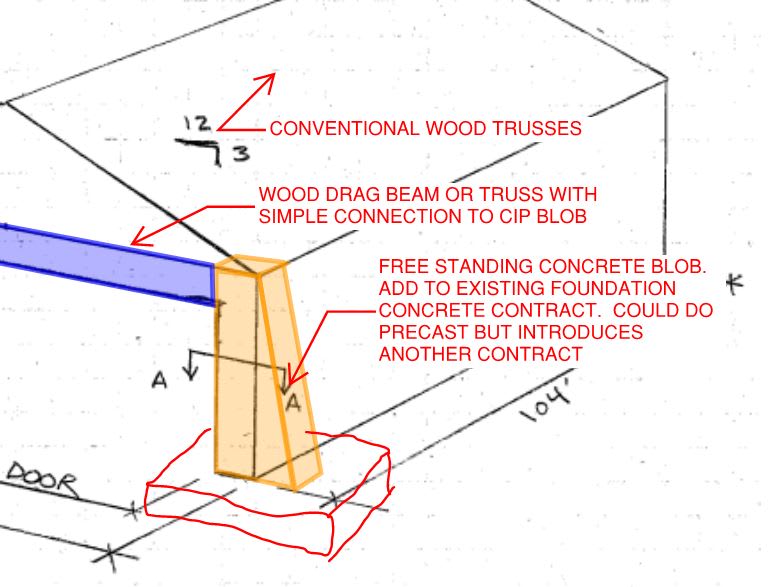
Please see attached sketch. I'm working on a preliminary design for a large building that will require some reinforcing with OSB/plyood. Due to the large 16'x70' bi-fold door, I'm left with just 5' wall segments each side of the opening for resisting lateral loads from wind. Using the ASCE 7-10 wind design criteria (115 mph, GCpi +/- 0.55, Risk Category C, etc.) and ASD load case 0.6D + 0.6W, I get unit shear of approx. 400 plf. This far exceeds the capacity of the exterior steel cladding (approx. 130 plf), but well within the capacity of 15/32" or 19/32" sheathing with a 4" or 6" edge fastener spacing. (Be sure to apply the 2.0 FS to the values in Table 4.3A). Perhaps there are some additional capacity reductions that are appropriate, considering the sheathing will be fastened to the flat face of wall girts, rather than edge of studs. But I'm thinking of doubling up the sheathing for a little peace of mind.
I'm studied the NFBA Post Frame Manual but it does not go into alot of detail on this topic. Is anyone aware of other publications that would do?

Any advice is appreciated!
 
 https://files.engineering.com/getfile.aspx?folder=7e7f5e8b-b2ca-4f86-bf1e-ff87585bd864&file=CCI_000006.pdf
Perhaps there are some additional capacity reductions that are appropriate, considering the sheathing will be fastened to the flat face of wall girts, rather than edge of studs.

I'm not sure there are adopted shear capacity tables for sheathing like this on spaced-out wall girts....are there?


Check out Eng-Tips Forum's Policies here:
faq731-376
 
Your wind loads seem low. Based on the 10 psf minimum on the projected area, you would have 100 plf load on the roof framing (10 psf * 40*3/12) + 92.5 plf on the walls (10psf x 18.5/2) = 192 plf wind load x 52 ft = 10.000 lbs or 1,000 plf. if you have 5 ft. of shearwall at each end. I would be looking at a steel framed end wall. Your tie-down forces are going to be in the range of 18.5 K.
 
TroyD:

This is going to be an extremely difficult building to design. It is much better suited for a PEMB. (pre-engineered metal building). The amount of detailing you will have to go thru to get this to work will be insane which also means it is unlikely to get built correctly. Just figuring out how to deal with the wind load on that door will be a challenge. I imagine if the client can afford an airplane, he can afford a better building.
 
TroyD:

I would add an extra vertical stud at the corner, one or two more studs in the middle, and put the sheathing on the inside face of the wall where you can nail to more stud material. Add hold downs to the multi-stud packages.

Where you have the sheathing now is merely an infill panel with a shorter width than what I propose.

Mike McCann, PE, SE (WA)


XR250 said:
I imagine if the client can afford an airplane, he can afford a better building.

For the majority of small airplane owners it's probably the opposite.

Ian Riley, PE, SE
Professional Engineer (ME, NH, MA) Structural Engineer (IL)
American Concrete Industries
 
XR250,
Thanks for the good input. I've been designing post frame structures for the last year or so with the help of the NFBA manual, misc. publications, and some good conversations on this discussion board. But I think this might be outside the capability of a post frame building. A steel framed end wall was initially discussed, and while I do have experience with designing foundations for PEMBs, I am not familiar and/or not comfortable with designing (and detailing) a goofy combination post frame / steel end wall.

I did run my wind loads again and got unit shear values similar to yours. Hey, one question I've always wondered: when using the minimum design wind loads in ASCE 7, Section 28.4.4 (16 psf walls/10 psf roofs), is it still acceptable to apply the 0.6D + 0.6W ASD load case? This helps my situation but not by much.

I have the specs packet on the 70' Schweiss bifold door. The max operational wind speed is 30 mph, otherwise "door must be closed with floor pins and locks engaged." I don't know what these floor pins look like but perhaps slim chance they can resist some lateral loading.

Thanks again,

-Troy
 
TroyD said:
Hey, one question I've always wondered: when using the minimum design wind loads in ASCE 7, Section 28.4.4 (16 psf walls/10 psf roofs), is it still acceptable to apply the 0.6D + 0.6W ASD load case? This helps my situation but not by much.

I have the specs packet on the 70' Schweiss bifold door. The max operational wind speed is 30 mph, otherwise "door must be closed with floor pins and locks engaged." I don't know what these floor pins look like but perhaps slim chance they can resist some lateral loading.

Thanks again,
I can't answer the wind load question as I am old school and still use ASD in 7-05 which uses 10 psf for everything. I doubt those door pins resist anything but shear. My recollection is the door spans horizontaly and trying to react those wind loads will be un-fun. Also, if that is a horizontally folding door, just the moment on the jambs from the gravity load huge. I have done a few residential airplane hanger garages and it was a very difficult to get that reactions form the Schweiss door to be resisted properly.

If it was me, I would run away from that job if they are dead set on a cheapo wood building.
 
Troy said:
is it still acceptable to apply the 0.6D + 0.6W ASD load case

Yes. Wind loads (including the minimum wind load cases) are ultimate loads in 7-10. Thus, if using ASD for wood you should reduce the wind loads. 0.6D + 0.6W is the appropriate load factors for uplift.

Ian Riley, PE, SE
Professional Engineer (ME, NH, VT, CT, MA) Structural Engineer (IL)
American Concrete Industries
 
Have you looked into strapping or a braced frame. Another option is to widen the structure by 10 feet or whatever to given yourself some extra wall length to work with.
 
I'd like to table an "out of the box" solution for your consideration. At first glance, it'll probably seem a little nuts. However, consider:

1) This is likely a building with minimal aesthetic constraints.

2) This is likely a building with minimal building envelope constraints.

3) This is likely a building for which there may already be a CIP foundation contract.

4) This would be supper easy to design. Effective a gravity retaining wall with a connection to your drag member.

5) If the buttressing allows this to be a wood building instead of a steel building, it may make sense economically.

6) If this would mean the mixing of shallow and deep foundation systems, that would be worthy of some consideration.

My experience is similar to TME's in that owners do not want to spend any money on the design or construction of these thing. Depending on the type of "post-frame" construction that is being contemplated here, there may not even be a serious concrete contract into which the buttresses could be added.

c01_nkbfjz.jpg
 
Status
Not open for further replies.

Part and Inventory Search

Sponsor

Back
Top