You still did not say which standard you are adhering to. I will assume Y14.5-2009 unless you say otherwise.
Position of one hole will be measure from datum and from that hole, another hole position will measured. Hence no symmetry. If the first hole is at exact position, the second hole can offset for the full geometric tolerance.
No. The tolerance zone is constrained only to the referenced datum features. In your initial example both holes must each fall within a 0.3 dia tolerance zone constrained to datum features |A|B|. The position of one hole does not dictate the allowed position of another unless one of those holes is referenced as a datum feature in the position FCF of the other. (Unless we are talking about MMC with unconstrained DOF or datum features referenced at MMB)
Single FCF for coaxial features, each feature will get bonus tolerance wrt the actual size.
Yes.
1) Which method (1 or 2 or 3) is correct and why other methods are wrong?
Methods 1 and 2 are an identical requirement. 3 holds the position of the counterbore more closely to the clearance hole. None are "wrong"* it only depends on your requirements. That said, you have dropped several datum feature references from each feature which I think are missing, unless that truly represents intent (I'd be skeptical of that). It seems to me that the DRF for the central hole position should be |A|B|C|, the position for each hole/counterbore in methods 1/2 (and clearance hole in method 3) should be wrt |A|D| and with either B or C as a clocking datum feature, unless you don't care where the holes are relative to B/C (doubtful). The position tolerance for the central hole and hole/counterbore in methods 1/2 (and clearance hole in 3) could actually be held in simultaneous requirements to |A|B|C| unless you truly need to hole the hole/counterbore to the central hole. The SIM REQT method is usually much cleaner and would prevent you having to decide which B or C to choose as a clocking datum feature**.
2) Is it possible to define single axis as a datum without affecting the orientation of the holes as displayed?
I don't follow. Please clarify what you mean.
3) Does the method 2, implies SIMULTANEOUS REQUIREMENT?
Yes, method 2 is subject to simultaneous requirements (SIM REQT). Note this only applies to the position tolerances.
4) Does the method 3, datum E is simulated from hole 1 for counter bore of hole 1 and datum E is
simulated from hole 2 for counter bore of hole 2?
Not the way you have it drawn - as shown in your attachment datum feature E would be the pattern of 2X holes. See below for a method outlined in the standard to accomplish what you describe.
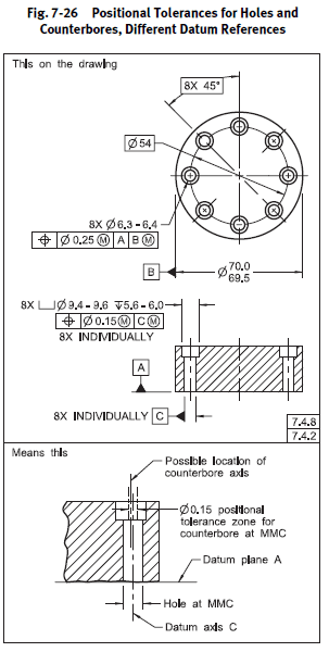
*I wouldn't say method 3 is "wrong" per se but I think what you are trying to accomplish is more akin to 7-26 from Y14.5-2009 below. The INDIVIDUALLY requirement creates a separate, individual datum feature for each clearance hole/counterbore pair.
**Edit - it is much more likely as well that the outer profile should be held in reference to the central hole/bolt holes and not the other way around, unless something truly interfaces/mates with B and C. Additionally if that is the case everything could be held in SIM REQT to A. Or the central hole to A, then the central hole designated B and everything else held to |A|B| including the outer profile. Either way, it likely reflects intent better than holding the holes relative to the outside profile.