JStructsteel
Structural
- Aug 22, 2002
- 1,451
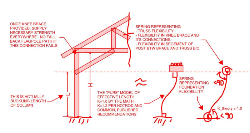
Looking at a pole barn, and trying to decide a Ky factor for my column. I know its not fixed, and i know its not free. Somewhere in between? Ky 1.6 keeps the column in check. Whats your opinions?
Follow along with the video below to see how to install our site as a web app on your home screen.
Note: This feature may not be available in some browsers.
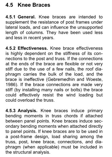
jrisebo said:Its a pole barn, so columns and kneed braces.
OP said:...and trying to decide a Ky factor for my column
jrisbo said:KootK, I suppose I really dont know the system name I am using.
jrisbo said:Thoughts?
jrisebo said:Its strange how the cheapest of buildings for a consumer provide the most questions/dilemmas for us engineers.