Continue to Site

Eng-Tips is the largest engineering community on the Internet

Intelligent Work Forums for Engineering Professionals

  • Congratulations KootK on being selected by the Eng-Tips community for having the most helpful posts in the forums last week. Way to Go!

Pipe Diameter design 1

Status
Not open for further replies.

Eng.Amir

Mechanical
Dec 14, 2022
4
Hi all,

I have a small problem I would like your help with. I am more interested in how to do the calculation so I can do it myself in the future.
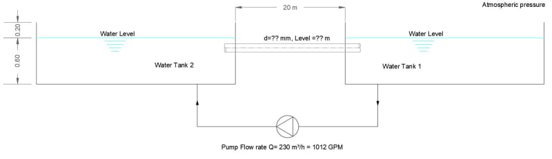
I have two tanks, different volumes but both has same level, I want to dimension the pipe (1 or more) between the two tanks.

see the attached drawing for a quick illustration, I use a 230 m³/h pump to deliver that flow from tank 1 to tank 2.
My question is how to calculate the needed pipe diameter in order to return back that flow to tank 1 by gravity? and what is the best level to install that pipe to be efficient.
Thanks for everyone can help in advance.
Capture_l5kiam.jpg
 
Replies continue below

Recommended for you

For there to be flow from Tank 2 to Tank 1 through the connecting pipe the level in Tank 2 must be higher than in Tank 1. So the real question is what difference in levels can you tolerate and once this is established you can size the equalizing pipe.

Katmar Software - AioFlo Pipe Hydraulics

"An undefined problem has an infinite number of solutions"
 
As with the other recent question here, the issue is one of a transient nature if this is a batch operation unless this is a steady state question?

SO what exactly is the operation as it seems a bit odd to pump or flow water in one direction then simply let it flow back again?

Your pump will have virtually no differential pressure so may be rather hard to find one that works.

And Katmar is correct as always. To define this you need to determine the max allowable head difference.

The location of the pipe is irrelevant as long as both ends are completely submerged. It might be best to set it at a slight angle so that there are no air pockets.

Remember - More details = better answers
Also: If you get a response it's polite to respond to it.
 
Hi Katmar,
Thanks for your reply
There are no possibility to make a level difference between the 2 tanks; (these are 2 fountains with same level) at the beginning of pump operation, the 2 tanks are equalized, but after 15 min, tank 1 level drops down while tank 2 level increases.
Here are the difference in levels that can be done.
So now what is the required diameter?
 
Just use the Manning equation for the pipe design. Let the pipe flow full. Size that pipe for full 230 m3/h flow at your minimum head difference, S = Head Difference / Length of pipe.
Fill the left tank to any height over the top of the pipe. Fill the right tank to the top of the pipe. Turn on the pump at 230 m3/h. Whatever minimum head difference you have chosen will then hold constant whenever the pump is flowing 230 m3/h.

Select, or control your pump to have a discharge head equal to the height of the water in the left tank when it's flow rate is 230 m3/h.


Einstein gave the same test to students every year. When asked why he would do something like that, "Because the answers had changed."
 
There must be some level difference or there will be no head and no flow.
So if we assume some small number that pushes the delta P very low and the pipe size very large.
Slopping the pipe is a very good idea. With low flow velocity it would be easy for air to partially block the pipe.
Just run some basic calculations, 20m, 230m3 flow, and some guesses at pressure difference (100mm, 200mm, 300mm) at different pipe sizes and see what works.

= = = = = = = = = = = = = = = = = = = =
P.E. Metallurgy, consulting work welcomed
 
If you cannot have a difference between the pool elevations, you will theoretically need an infinite pipe diameter. Good luck with that.

I suggest you use the largest pipe diameter you can fit into the wall and live with whatever slope S results, given the pipe diameter you do select. If still too much S, you will need to add more pipes of the same diameter.


Einstein gave the same test to students every year. When asked why he would do something like that, "Because the answers had changed."
 
The only other alternative is to put a pump in the cross flow pipe too.

Einstein gave the same test to students every year. When asked why he would do something like that, "Because the answers had changed."
 
Amir,

I think you misunderstood the comment. What Katmar and everyone else is telling you is that the WATER LEVEL between the two tanks needs to be different for any flow to occur in that interconnecting pipe, not the actual level of the tank.

Now looking at your sketch again, the max difference in height before tank 2 overflows is 0.4 of a m assuming both tanks are the same volume AND no more water is added anywhere. In reality lets say it's a bit lower than max so a max difference of 300mm.

Over 20m that gives you a slope of 0.015.

I used an online calculator for full pipe manning flow and for your flow rate came up with an ID of about 220mm / an 8" pipe. Prob best to put a slightly larger one in, say 250 NB.

There are lots of others

Remember - More details = better answers
Also: If you get a response it's polite to respond to it.
 
given that the lower tank will gradually fill up, the height difference between the two tanks will (on average) be less than 300mm. suggest using half of that. also, suggest including an inlet loss which will further reduce your flow. so your pipe size is likely going to be significantly larger
 
I think this is being over-engineered. my understanding of the system is you are pumping from tank 1 to a fountain in tank 2, so you are looking at a return flow back to tank 1 (like a balance pipe between storage tanks).
if you are pumping out at 230m3/h your return flow should also be the same. If the return pipe length is short you may be able to ignore friction loss, and just size a pipe for 230m3/hr at less than 1m/s so minimum ID of 300mm
If the friction losses result in flow being less than 230m3/h the level in tank 1 will slowly drop and eventually the head difference will result in the balance pipe flows increasing and i suspect it will result in a state of equilibrium while the pump is running (but i doubt this will be noticeable unless the pump works 24-7-365). If this is a concern maybe reduce flow velocity to 0.5m/s so 375+mm pipe
 
Thank you all for your help I really appreciate.
And special thanks to LittleInch for your attached link, It really helps a lot.
I will execute on site the calculated pipe and let's see the outcome.
 
AMir,

The trick in design is first define your parameters. In this case, what is the maximum water level difference that is acceptable to you form a visual point of view and doesn't result in an overflow. After that it's the engineering.

Please come back to us and let us know how it works and pictures are always appreciated, as is a response.

Remember - More details = better answers
Also: If you get a response it's polite to respond to it.
 
LittleInch,
Sure I will come back to you with photos, let me 2 or 3 weeks.
 
Status
Not open for further replies.

Part and Inventory Search

Sponsor